Ariens Hydro Pro Track 32 Owners Manual - Page 12
Socket Extension Optional, Discharge Chute Ring
 |
View all Ariens Hydro Pro Track 32 manuals
Add to My Manuals
Save this manual to your list of manuals |
Page 12 highlights
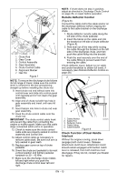
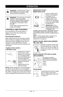
NOTE: Leave discharge chute pedestal loose to help install the chute rod. 3 1 OS7040 2 4 2 1 5 3 1. Mounting Holes 2. Discharge Chute 3. Discharge Chute Ring 4. Chute Pedestal 5. Mounting Hardware Figure 5 4. Remove the gear cover from top of chute pedestal. 5. Release the lock teeth on the gear assembly with your finger and rotate the discharge chute so it points straight ahead. NOTE: Make sure alignment markers are lined up when discharge chute is pointing straight ahead. 6. Remove rubber grommet from control panel. 7. Make sure the chute control cable is routed between the lower handlebar and the bottom of the control panel, insert control assembly into slot in control panel from below and install assembly into nylon bushing in control panel. 4 5 32 1 1. Control Assembly 2. Nylon Bushing 3. Push Nut 4. Socket Extension (Optional) 5. Socket, 3/4" Figure 6 8. Reinstall rubber grommet over control assembly knob and into control panel. EN - 12
-
 1
1 -
2
-
3
-
4
-
5
-
6
-
 7
7 -
 8
8 -
 9
9 -
 10
10 -
 11
11 -
 12
12 -
 13
13 -
 14
14 -
 15
15 -
 16
16 -
 17
17 -
18
-
19
-
20
-
21
-
22
-
23
-
24
-
25
-
26
-
27
-
28
-
29
-
30
-
31
-
32
-
33
-
34
-
35
-
36
-
37
-
38
-
39
-
40
-
41
-
42
 |
 |
