Asus A7V-E Motherboard DIY Troubleshooting Guide - Page 37
A7V-E System Panel Connectors
 |
View all Asus A7V-E manuals
Add to My Manuals
Save this manual to your list of manuals |
Page 37 highlights
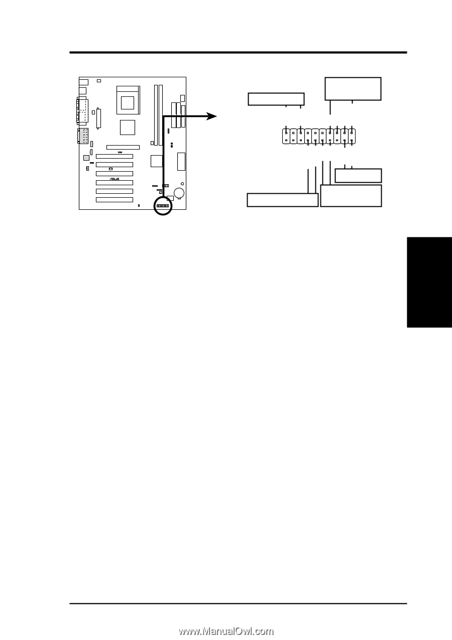
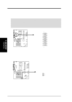
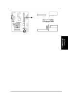
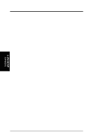
3. HARDWARE SETUP The following PANEL illustration is used for items 21-25. 01 01 Power LED Speaker Connector PLED+ PLED+5V Ground Ground Speaker ExtSMI# Ground PWR GND Reset Ground 3. H/W SETUP Connectors Reset SW ® ATX Power SMI Lead Switch* A7V-E * Requires an ATX power supply. A7V-E System Panel Connectors 22) System Warning Speaker Connector (4-pin SPEAKER) This 4-pin connector connects to the case-mounted speaker. Two sources (LINE_OUT and SPEAKER) will allow you to hear system beeps and warnings. Only SPEAKER will allow you to hear system beeps before the integrated audio has been properly initialized. 23) System Power LED Lead (3-1 pin PWRLED) This 3-1 pin connector connects the system power LED, which lights when the system is powered on and blinks when it is in sleep mode. 24) Reset Switch Lead (2-pin RESET) This 2-pin connector connects to the case-mounted reset switch for rebooting your computer without having to turn off your power switch. This is a preferred method of rebooting to prolong the life of the system's power supply. 25) ATX Power Switch Lead (2-pin PWRSW) The system power is controlled by a momentary switch connected to this lead. Pressing the button once will switch the system between ON and SOFT OFF. Pushing the switch while in the ON mode for more than 4 seconds will turn the system off. The system power LED shows the status of the system's power. 26) System Management Interrupt Lead (2-pin SMI) This allows the user to manually place the system into a suspend mode or "Green" mode, where system activity is decreased to save electricity and expand the life of certain components when the system is not in use. This 2-pin connector connects to the case-mounted suspend switch. If you do not have a switch for the connector, you may use the "Turbo Switch." SMI is activated when it detects a short to open moment and therefore leaving it shorted will not cause any problems. This may require one or two presses depending on the position of the switch. Wake-up can be controlled by settings in the BIOS but the keyboard will always allow wake-up (the SMI lead cannot wake up the system). ASUS A7V-E User's Manual 37
-
 1
1 -
2
-
3
-
4
-
5
-
6
-
7
-
8
-
9
-
10
-
11
-
12
-
13
-
14
-
15
-
16
-
17
-
18
-
19
-
20
-
21
-
22
-
23
-
24
-
25
-
26
-
27
-
28
-
29
-
30
-
31
-
 32
32 -
 33
33 -
 34
34 -
 35
35 -
 36
36 -
 37
37 -
 38
38 -
 39
39 -
 40
40 -
 41
41 -
 42
42 -
43
-
44
-
45
-
46
-
47
-
48
-
49
-
50
-
51
-
52
-
53
-
54
-
55
-
56
-
57
-
58
-
59
-
60
-
61
-
62
-
63
-
64
-
65
-
66
-
67
-
68
-
69
-
70
-
71
-
72
-
73
-
74
-
75
-
76
-
77
-
78
-
79
-
80
-
81
-
82
-
83
-
84
 |
 |