Asus A7V133 A7V133 User Manual - Page 14
Hardware Setup - not powering up
 |
View all Asus A7V133 manuals
Add to My Manuals
Save this manual to your list of manuals |
Page 14 highlights
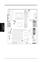
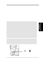
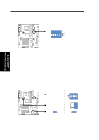
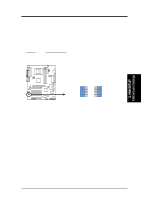
Socket 462 DIMM3 (64/72 bit, 168-pin module) DIMM2 (64/72 bit, 168-pin module) DIMM1 (64/72 bit, 168-pin module) ATX Power Connector PRIMARY IDE FLOPPY 30.6cm (12in) 3. H/W SETUP Motherboard Layout 3. HARDWARE SETUP 3.1 Motherboard Layout PS/2 T: Mouse B: Keyboard USB T: Port0 B: Port1 COM1 24.5cm (9.64in) JTPWR 01 01 01 PWR_FAN VIO 3VSBSLT CLRTC CR2032 3V Lithium Cell CMOS Power SK7VRM PARALLEL PORT GAME_AUDIO COM2 Line Out Line In Mic In VID4 VID3 VID2 VID1 F_FAN CPU_FAN VIA VT8363A AGP4X & PC133 Memory Controller DIP Switches DSW DSFID CHA_FAN Row 5 4 3 2 1 0 SECONDARY IDE SECONDARY Ultra ATA100 IDE 2Mbit Flash EEPROM (Programmable BIOS) PRIMARY Ultra ATA100 IDE CD AUX MIC2 Audio Codec Accelerated Graphic Port (AGP PRO) PLED SMB PCI Slot 1 PCI Slot 2 VIA VT82C686B ATA100 IDE Controller MODEM SPK ADN# AUD_EN2 AUD_EN1 PCI Slot 3 PCI Slot 4 A7V133 WOLCON PCI Slot 5 Audio Modem Riser (AMR) WOR ASUS ASIC JEN AS99127F USBPORT CHASSIS JP13 JP14 IR IDELED PANEL Grayed components are optional at the time of purchase (JTCPU is no longer necessary on motherboards with PCB versions 1.02 and later) 14 ASUS A7V133 User's Manual
-
 1
1 -
2
-
3
-
4
-
5
-
6
-
7
-
8
-
 9
9 -
 10
10 -
 11
11 -
 12
12 -
 13
13 -
 14
14 -
 15
15 -
 16
16 -
 17
17 -
 18
18 -
 19
19 -
20
-
21
-
22
-
23
-
24
-
25
-
26
-
27
-
28
-
29
-
30
-
31
-
32
-
33
-
34
-
35
-
36
-
37
-
38
-
39
-
40
-
41
-
42
-
43
-
44
-
45
-
46
-
47
-
48
-
49
-
50
-
51
-
52
-
53
-
54
-
55
-
56
-
57
-
58
-
59
-
60
-
61
-
62
-
63
-
64
-
65
-
66
-
67
-
68
-
69
-
70
-
71
-
72
-
73
-
74
-
75
-
76
-
77
-
78
-
79
-
80
-
81
-
82
-
83
-
84
-
85
-
86
-
87
-
88
-
89
-
90
-
91
-
92
-
93
-
94
-
95
-
96
-
97
-
98
-
99
-
100
-
101
-
102
 |
 |
