Asus A7V133 A7V133 User Manual - Page 92
Alternative Set Ups and Other Details
 |
View all Asus A7V133 manuals
Add to My Manuals
Save this manual to your list of manuals |
Page 92 highlights
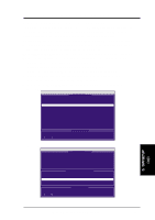
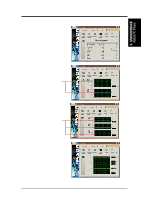
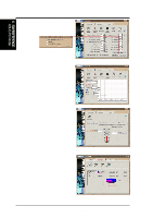
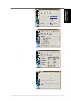
5. SOFTWARE SETUP 8. Confirm the command to copy data from the intact source hard disk onto a new replacement hard disk. A progress gauge displays the copy progress for the duration of the task. 9. After the rebuild is complete, the user is prompted to reboot the system. Controller Configuration (6): Default for Controller Configuration is: [enabled]. 5.4.6 Alternative Set Ups and Other Details Hot Spares A "Hot" spare hard disk may be installed to support a RAID 1 array. This spare hard disk can share one of the Ultra-DMA/100 cables, but is not assigned to the array. In the event of a failure on one of the active hard disks used in the array, the "Lite" BIOS system detects the "Hot" spare and automatically rebuilds the mirrored data from the functional hard disk, and effectively establishes a new but identical array. Use Both ATA-100 Connectors Optimal performance for RAID 0 and 1 arrays require that each hard disk be connected to separate IDE channels; the first hard disk should be connected to the Primary ATA-100 connector and the second hard disk, to the Secondary ATA-100 connector. Adding Extra Hard Disks The A7V133 is supplied with two addal Primary IDE and Secondary IDE connectors. Extra hard disks can be connected to the system using these onboard IDE connectors, but such disks cannot be configured to make a RAID array. In principle, up to eight hard disks may connect to the A7V133. However, only two "master" hard disks connected to the Primary and Secondary ATA-100 IDE connectors can function in a RAID 0 or RAID 1 array. Up to six extra disks connected to the A7V133 will default to function at ATA-100 standard. If jumpers are reset to the default ATA-100 position, then up to eight hard disks can be connected to function with this protocol. Use ATA-100, High-RPM Hard Disks with Identical Storage Capacity The fastest available hard disks should be used in the RAID 0 array to maximize performance. Slower hard disks may be used; however, the RAID 0 array can only double the speed of particular hard disks. Since you can achieve better performance with a single ATA-100 hard disk than with two ATA-33 disks in a RAID 0 array, it is more effective to install two ATA-100 or ATA-66 high-RPM hard disks for an array. Hard disks used for both RAID 0 and 1 arrays should always have the same storage capacity because the RAID protocol automatically formats both disks to use only up to the maximum write space available on the smaller of two different hard disks. End-to-End Cable Connection Use only the ends of cable connectors to avoid signal loss mid-stream. 5. S/W SETUP RAID 92 ASUS A7V133 User's Manual
-
 1
1 -
2
-
3
-
4
-
5
-
6
-
7
-
8
-
9
-
10
-
11
-
12
-
13
-
14
-
15
-
16
-
17
-
18
-
19
-
20
-
21
-
22
-
23
-
24
-
25
-
26
-
27
-
28
-
29
-
30
-
31
-
32
-
33
-
34
-
35
-
36
-
37
-
38
-
39
-
40
-
41
-
42
-
43
-
44
-
45
-
46
-
47
-
48
-
49
-
50
-
51
-
52
-
53
-
54
-
55
-
56
-
57
-
58
-
59
-
60
-
61
-
62
-
63
-
64
-
65
-
66
-
67
-
68
-
69
-
70
-
71
-
72
-
73
-
74
-
75
-
76
-
77
-
78
-
79
-
80
-
81
-
82
-
83
-
84
-
85
-
86
-
 87
87 -
 88
88 -
 89
89 -
 90
90 -
 91
91 -
 92
92 -
 93
93 -
 94
94 -
 95
95 -
 96
96 -
 97
97 -
98
-
99
-
100
-
101
-
102
 |
 |
