Asus A7V133 A7V133 User Manual - Page 20
of Software Setup: Using the Promise Chip for RAID 0 or 1. - manual
 |
View all Asus A7V133 manuals
Add to My Manuals
Save this manual to your list of manuals |
Page 20 highlights
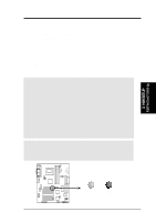
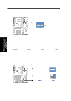
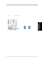
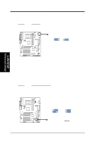
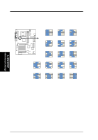
01 01 01 01 01 01 3. HARDWARE SETUP 4) PCI 3Volt Setting (3VSBSLT) This jumper allows you to select the voltage supplied to PCI devices. If you have PCI devices that require auxiliary power, set this jumper to 3 VSB. Setting 3 Volt 3 VSB 3VSBSLT [1-2] [2-3] (default) 3VSBSLT 12 23 Add 3 Volt Add 3 VSB (Default) A7V133 A7V133 PCI 3Volt Selection 5) ATA100 / RAID 0 or 1 Setting (ATA100/RAID 0 or 1) Jumper 13 and 14 specifies the function of the Promise IDE controller. Changing the jumper allows you to select the ATA100 IDE protocol or the RAID 0 and 1 protocol. NOTE: You will need to shift your IDE device connections if changing this setting: see page 36, More information is available in Section 5.4 of Software Setup: Using the Promise Chip for RAID 0 or 1. The default setting is ATA100: [1-2] [1-2]. Setting RAID 0 or 1 ATA100 ATA100/RAID 0 or 1 Jumper 13 [1-2] Jumper 14 [2-3] Jumper 13 [1-2] Jumper 14 [1-2] 3. H/W SETUP Motherboard Settings 21 21 JP13 JP14 32 RAID 0 or 1 ATA100 A7V133 A7V133 ATA100/RAID0 Selection (Default) ASUS A7V133 User's Manual
-
 1
1 -
2
-
3
-
4
-
5
-
6
-
7
-
8
-
9
-
10
-
11
-
12
-
13
-
14
-
 15
15 -
 16
16 -
 17
17 -
 18
18 -
 19
19 -
 20
20 -
 21
21 -
 22
22 -
 23
23 -
 24
24 -
 25
25 -
26
-
27
-
28
-
29
-
30
-
31
-
32
-
33
-
34
-
35
-
36
-
37
-
38
-
39
-
40
-
41
-
42
-
43
-
44
-
45
-
46
-
47
-
48
-
49
-
50
-
51
-
52
-
53
-
54
-
55
-
56
-
57
-
58
-
59
-
60
-
61
-
62
-
63
-
64
-
65
-
66
-
67
-
68
-
69
-
70
-
71
-
72
-
73
-
74
-
75
-
76
-
77
-
78
-
79
-
80
-
81
-
82
-
83
-
84
-
85
-
86
-
87
-
88
-
89
-
90
-
91
-
92
-
93
-
94
-
95
-
96
-
97
-
98
-
99
-
100
-
101
-
102
 |
 |
