Asus A7VL133-VM Motherboard DIY Troubleshooting Guide - Page 28
Universal Serial BUS Ports 0 & 1 Black two 4-pin USB
 |
View all Asus A7VL133-VM manuals
Add to My Manuals
Save this manual to your list of manuals |
Page 28 highlights
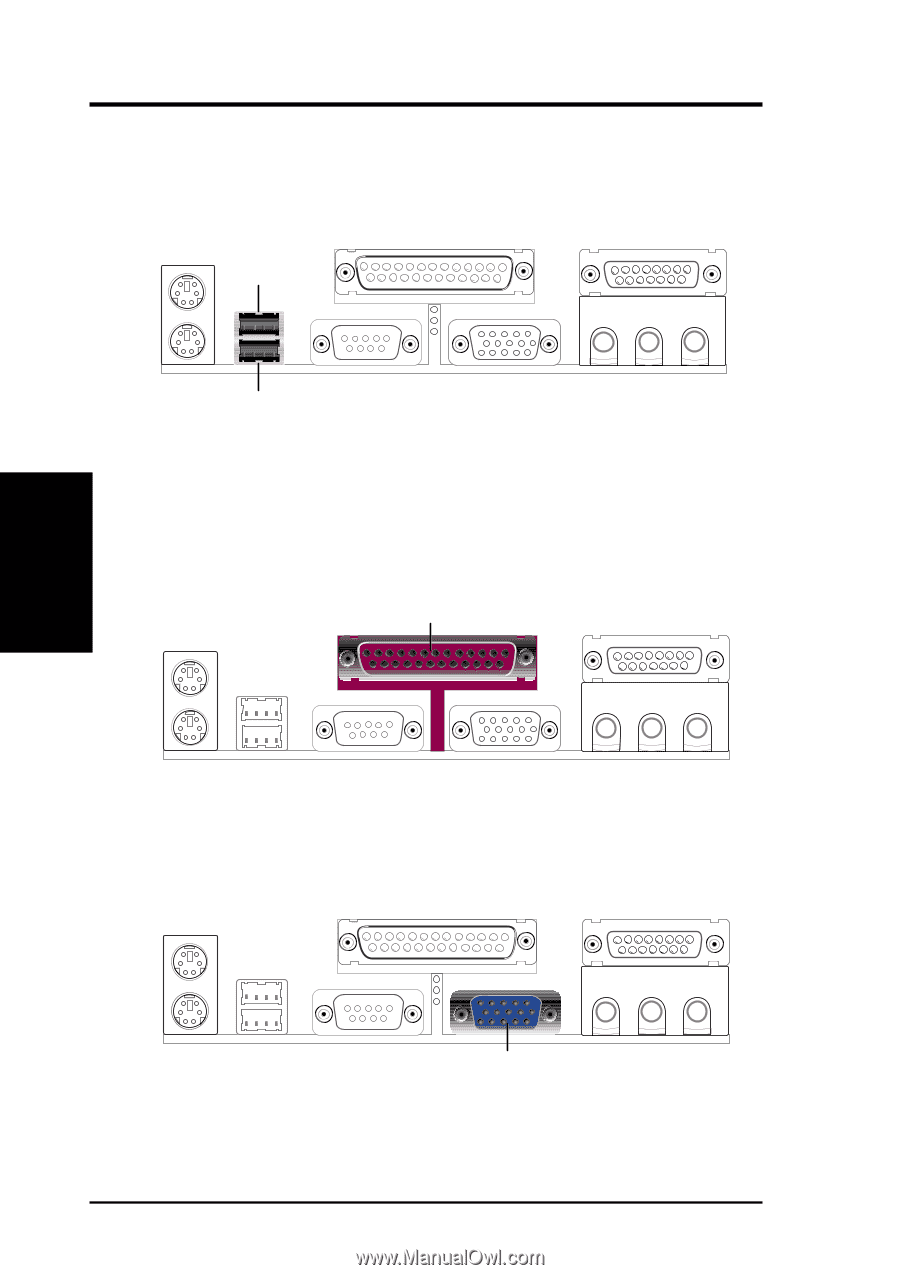
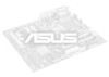
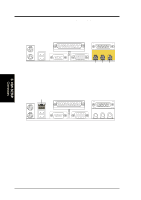
3. HARDWARE SETUP 3) Universal Serial BUS Ports 0 & 1 (Black two 4-pin USB) Two USB ports are available for connecting USB devices. For additional USB ports, you can use the USB headers (see USB Headers later in this section) and mount it to the chassis. USB 1 Universal Serial Bus (USB) 2 4) Parallel Port Connector (Burgundy 25-pin PRINTER) You can enable the parallel port and choose the IRQ through Onboard Parallel Port (see 4.4.2 I/O Device Configuration). NOTE: Serial printers must be connected to the serial port. Parallel (Printer) Port (25-pin female) 3. H/W SETUP Connectors 5) Monitor Output Connector (Blue 15-pin VGA) This connector is for output to a VGA-compatible device. VGA Monitor (15-pin female) 28 ASUS A7VL133-VM User's Manual
-
 1
1 -
2
-
3
-
4
-
5
-
6
-
7
-
8
-
9
-
10
-
11
-
12
-
13
-
14
-
15
-
16
-
17
-
18
-
19
-
20
-
21
-
22
-
 23
23 -
 24
24 -
 25
25 -
 26
26 -
 27
27 -
 28
28 -
 29
29 -
 30
30 -
 31
31 -
 32
32 -
 33
33 -
34
-
35
-
36
-
37
-
38
-
39
-
40
-
41
-
42
-
43
-
44
-
45
-
46
-
47
-
48
-
49
-
50
-
51
-
52
-
53
-
54
-
55
-
56
-
57
-
58
-
59
-
60
-
61
-
62
-
63
-
64
-
65
-
66
-
67
-
68
-
69
-
70
-
71
-
72
-
73
-
74
-
75
-
76
-
77
-
78
-
79
-
80
-
81
-
82
-
83
-
84
-
85
-
86
-
87
-
88
-
89
-
90
-
91
-
92
-
93
-
94
-
95
-
96
 |
 |