Asus A7VL133-VM Motherboard DIY Troubleshooting Guide - Page 32
Standard and Consumer Infrared Module Connector 5 pin IR
 |
View all Asus A7VL133-VM manuals
Add to My Manuals
Save this manual to your list of manuals |
Page 32 highlights
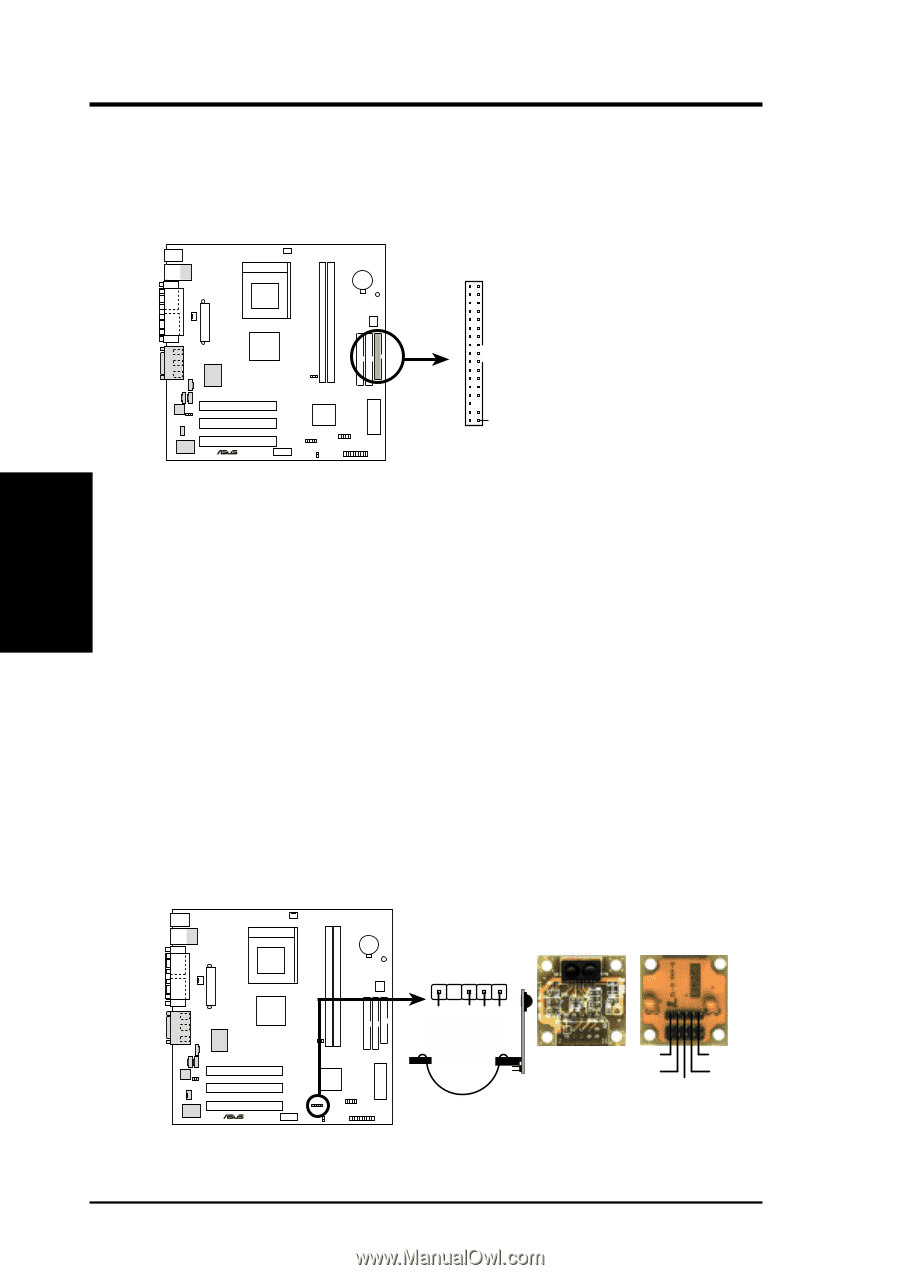
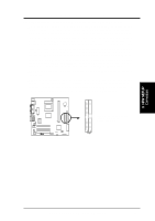
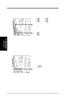
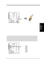
3. HARDWARE SETUP 11) Floppy Disk Drive Connector (34-1 pin FLOPPY) This connector supports the provided floppy drive ribbon cable. After connecting the single end to the board, connect the two plugs on the other end to the floppy drives. (Pin 5 is removed to prevent inserting in the wrong orientation when using ribbon cables with pin 5 plugged). NOTE: Orient the red markings on the floppy ribbon cable to PIN 1 A7VL133-VM PIN 1 ® A7VL133-VM Floppy Disk Drive Connector 3. H/W SETUP Connectors 12) Standard and Consumer Infrared Module Connector (5 pin IR) This connector supports an optional wireless transmitting and receiving infrared module. This module mounts to a small opening on system cases that support this feature. You must also configure the setting through UART2 Use Infrared (see 4.4.2 I/O Device Configuration) to select whether UART2 is directed for use with COM2 or IrDA. Use the five pins as shown in Back View and connect a ribbon cable from the module to the motherboard's SIR connector according to the pin definitions. IR 1 Front View Back View +5V IRRX GND IRTX A7VL133-VM ® A7VL133-VM Infrared Module Connector IRTX GND IRRX +5V (NC) 32 ASUS A7VL133-VM User's Manual
-
 1
1 -
2
-
3
-
4
-
5
-
6
-
7
-
8
-
9
-
10
-
11
-
12
-
13
-
14
-
15
-
16
-
17
-
18
-
19
-
20
-
21
-
22
-
23
-
24
-
25
-
26
-
 27
27 -
 28
28 -
 29
29 -
 30
30 -
 31
31 -
 32
32 -
 33
33 -
 34
34 -
 35
35 -
 36
36 -
 37
37 -
38
-
39
-
40
-
41
-
42
-
43
-
44
-
45
-
46
-
47
-
48
-
49
-
50
-
51
-
52
-
53
-
54
-
55
-
56
-
57
-
58
-
59
-
60
-
61
-
62
-
63
-
64
-
65
-
66
-
67
-
68
-
69
-
70
-
71
-
72
-
73
-
74
-
75
-
76
-
77
-
78
-
79
-
80
-
81
-
82
-
83
-
84
-
85
-
86
-
87
-
88
-
89
-
90
-
91
-
92
-
93
-
94
-
95
-
96
 |
 |