Asus A7VL133-VM Motherboard DIY Troubleshooting Guide - Page 35
ASUS A7VL133-VM User's Manual, USB Header 10-1 pin USB2, ATX Power Supply Connector, pin block
 |
View all Asus A7VL133-VM manuals
Add to My Manuals
Save this manual to your list of manuals |
Page 35 highlights
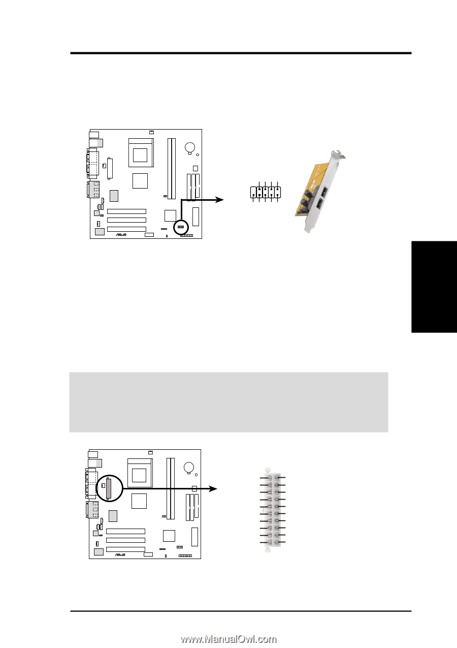
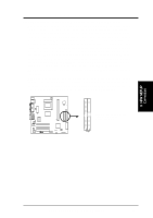
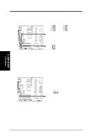
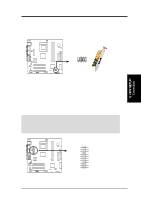
3. HARDWARE SETUP 16) USB Header (10-1 pin USB2) If the USB port connectors on the back panel are inadequate, this USB header is available for two additional USB port connectors. Connect the USB headers to the 2-port USB connector set and mount the bracket to an open slot on your chassis. A7VL133-VM ® A7VL133-VM USB Port USB Power USBP2- USBP2+ GND NC USB Power USBP3- USBP3+ GND USB2 10 6 5 1 3. H/W SETUP Connectors 17) ATX Power Supply Connector (20 pin block ATXPWR) This connector connects to an ATX power supply. The plug from the power supply will only insert in one orientation because of the different hole sizes. Find the proper orientation and push down firmly making sure that the pins are aligned. IMPORTANT: Make sure that your ATX power supply can supply at least 10mA on the +5-volt standby lead (+5VSB). You may experience difficulty in powering ON your system if your power supply cannot support the load. For WakeOn-LAN support, your ATX power supply must supply at least 720mA +5VSB. A7VL133-VM ® +3.3 Volts -12.0 Volts Ground Power Supply On Ground Ground Ground -5.0 Volts +5.0 Volts +5.0 Volts A7VL133-VM ATX Power Connector +3.3 Volts +3.3 Volts Ground +5.0 Volts Ground +5.0 Volts Ground Power Good +5V Standby +12.0 Volts ASUS A7VL133-VM User's Manual 35
-
 1
1 -
2
-
3
-
4
-
5
-
6
-
7
-
8
-
9
-
10
-
11
-
12
-
13
-
14
-
15
-
16
-
17
-
18
-
19
-
20
-
21
-
22
-
23
-
24
-
25
-
26
-
27
-
28
-
29
-
 30
30 -
 31
31 -
 32
32 -
 33
33 -
 34
34 -
 35
35 -
 36
36 -
 37
37 -
 38
38 -
 39
39 -
 40
40 -
41
-
42
-
43
-
44
-
45
-
46
-
47
-
48
-
49
-
50
-
51
-
52
-
53
-
54
-
55
-
56
-
57
-
58
-
59
-
60
-
61
-
62
-
63
-
64
-
65
-
66
-
67
-
68
-
69
-
70
-
71
-
72
-
73
-
74
-
75
-
76
-
77
-
78
-
79
-
80
-
81
-
82
-
83
-
84
-
85
-
86
-
87
-
88
-
89
-
90
-
91
-
92
-
93
-
94
-
95
-
96
 |
 |