Asus AP140R AP140R User Manual English Edition
Asus AP140R Manual
 |
View all Asus AP140R manuals
Add to My Manuals
Save this manual to your list of manuals |
Asus AP140R manual content summary:
- Asus AP140R | AP140R User Manual English Edition - Page 1
® AP140R Pentium® 4 1U Rackmount Server User's Manual - Asus AP140R | AP140R User Manual English Edition - Page 2
revision number. For previous or updated manuals, BIOS, drivers, or product release information, contact ASUS at http://www.asus.com.tw or through any of the means indicated on the following page. SPECIFICATIONS AND INFORMATION CONTAINED IN THIS MANUAL ARE FURNISHED FOR INFORMATIONAL USE ONLY, AND - Asus AP140R | AP140R User Manual English Edition - Page 3
Contents Disclaimer/Copyrights 2 ASUS Contact Information 6 FCC/CDC Statements 7 Safety Precautions 8 Introduction About This Manual 9 Audience 10 Contents 10 Conventions 11 References 11 System Package Contents 12 Chapter 1 System Overview 13 1.1 System Features 14 1.2 Front Panel - Asus AP140R | AP140R User Manual English Edition - Page 4
Contents 2.4 Hard Drive Connector Boards 21 2.5 Installing a Hard Disk Drive 22 Install the HDD 22 Drive Trays 22 Mount the Hard Drive 22 2.5 Installing a Hard Disk Drive 23 IDE HDD and Power Cable Configurations 23 Motherboard IDE Connectors 23 2.6 Installing an Expansion Card 25 PCI Riser - Asus AP140R | AP140R User Manual English Edition - Page 5
Contents 3.3 Cooling System 34 Chassis Fans 34 3.4 Cable Connections 35 Appendix A Power Supply 37 A.1 General Description 38 A.2 Specifications 39 Output Voltage Regulation 39 Output Current Capacity 39 Over-Voltage Protection (OVP 39 Appendix B Troubleshooting 41 B.1 Simple Fixes 42 5 - Asus AP140R | AP140R User Manual English Edition - Page 6
Email: 150 Li-Te Road, Peitou, Taipei, Taiwan 112 +886-2-2894-3447 +886-2-2894-3449 [email protected] Technical Support MB/Others (Tel): Notebook (Tel): Desktop/Server (Tel): Support Fax: Support Email: Web Site: Newsgroup: +886-2-2890-7121 (English) +886-2-2890-7122 (English) +886-2-2890-7123 - Asus AP140R | AP140R User Manual English Edition - Page 7
. This equipment generates, uses and can radiate radio frequency energy and, if not installed and used in accordance with manufacturer's instructions, may cause harmful interference to radio communications. However, there is no guarantee that interference will not occur in a particular installation - Asus AP140R | AP140R User Manual English Edition - Page 8
must be conducted by certified or experienced engineers. • Before operating the server, carefully read all the manuals included with the server package. • Before using the server, make sure all cables are correctly connected and the power cables are not damaged. If any damage is detected, contact - Asus AP140R | AP140R User Manual English Edition - Page 9
About This Manual Introduction "About This Manual" introduces the contents of this document. This part includes the target audience, chapter description, and conventions used. It also lists other sources of information that are not contained in this manual. AP140R Server User's Manual 9 - Asus AP140R | AP140R User Manual English Edition - Page 10
Troubleshooting This appendix lists the common problems that you may encounter while using the server. It lists the possible causes of the problems and offers solutions. You may refer to this part and try to solve simple problems before calling customer support. 10 Introduction: About This Manual - Asus AP140R | AP140R User Manual English Edition - Page 11
ASUS websites are listed in the ASUS Contact Information on page 6. 3. Other Documentation Your product package may include other documentation, such as component manuals, inserts, stickers, or notices. Read all documentation before assembling or modifying the server. AP140R Server User's Manual - Asus AP140R | AP140R User Manual English Edition - Page 12
• CPU Heatsink (without fan) • AC Power Cord • This System User's Manual ASUS NB-LM Motherboard • 32-bit/33MHz PCI Riser Card • Support CD with Drivers and Utilities • Motherboard User's Manual Slide Rail Assembly (Rail Kit) • Server-side and rack-side rails • Mounting Ears Assembly • Rail Kit User - Asus AP140R | AP140R User Manual English Edition - Page 13
Chapter 1 This chapter describes the general features of the server. This includes sections on front panel, rear panel, and internal features of the server. System Overview AP140R Server User's Manual 13 - Asus AP140R | AP140R User Manual English Edition - Page 14
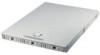
The ASUS AP140R Server is a 1U rackmount form factor that accommodates the ASUS NB-LM motherboard. The server is powered by Intel® Pentium® 4 processor, and supports the latest I/O and video technologies through the chipsets embedded on the motherboard. Following are highlights of the server's many - Asus AP140R | AP140R User Manual English Edition - Page 15
Floppy Drive Hard Drive Bay 0 Hard Drive Bay 1 Hard Drive Bay 2 1.3 Rear Panel Features The server rear panel includes the connectors the system devices and a slot for an expansion card. 1 2 3 VGA Port 7. LAN1 Port (RJ-45) 8. LAN2 Port (RJ-45) 9. Expansion Slot AP140R Server User's Manual 15 - Asus AP140R | AP140R User Manual English Edition - Page 16
include the motherboard, power supply, floppy and CD-ROM drives, and cables. The picture below shows the standard components of the server. 1 23 4 15 14 13 12 11 10 5 (Top) 6 (Bottom) 7 8 (Top) 9 (Bottom) 1. Power Supply 2. Power Supply Fan 3. CPU Blower 4. Floppy Ribbon Cable 5. Floppy - Asus AP140R | AP140R User Manual English Edition - Page 17
Chapter 2 This chapter describes the hardware setup procedures that you have to perform when installing system components. Hardware Setup AP140R Server User's Manual 17 - Asus AP140R | AP140R User Manual English Edition - Page 18
2.1 Opening the Chassis The chassis is a 1U form factor designed for easy assembly and disassembly, making the installation of internal components very convenient. At the top of the chassis is a rotating lock that secures the cover to the chassis. Rotating Lock Unlock the Cover To unlock the cover, - Asus AP140R | AP140R User Manual English Edition - Page 19
chassis. Do not overtighten the screws. Doing so may damage the motherboard. Note: This corner screw hole is used to secure the fan partition bracket. AP140R Server User's Manual 19 - Asus AP140R | AP140R User Manual English Edition - Page 20
comes with a specially designed heatsink as shown here. The heatsink has four screws to secure it to the server chassis underneath the motherboard. Install the Heatsink Place the heatsink on top of the installed CPU matching the four screws to the holes around the - Asus AP140R | AP140R User Manual English Edition - Page 21
2.4 Hard Drive Connector Boards The server comes with three externally accessible drive bays connected to the IDE back plane by swappable connectors. IDE Back Plane Drive Tray Connector Hard Drive Tray Board IDE Back Plane Side Hard Drive Tray Board Hard Drive Side AP140R Server User's Manual 21 - Asus AP140R | AP140R User Manual English Edition - Page 22
connector board using the original two screws. Example: IBM hard drive's default is "Master". Connector Board You must change to "Cable Select" for this server. Install the Hard Drive After the drive is secured to the tray, carefully insert the drive into the bay, then push the levers back into - Asus AP140R | AP140R User Manual English Edition - Page 23
0 and CD-ROM Power Cable for Hard Drive Back Plane Power Cable for CD-ROM Motherboard IDE Connectors The motherboard has two IDE connectors that support four IDE devices on two channels. Each channel supports one master and one slave device, for a total of four. AP140R Server User's Manual 23 - Asus AP140R | AP140R User Manual English Edition - Page 24
24 Chapter 2: Hardware Setup - Asus AP140R | AP140R User Manual English Edition - Page 25
Tab beside the riser card holder. 3. Remove the PCI Slot Cover from the rear panel. Locking Tab Riser Card Holder Riser Card PCI Slot Cover AP140R Server User's Manual 25 - Asus AP140R | AP140R User Manual English Edition - Page 26
2.6 Installing an Expansion Card Install the PCI Card Riser Card 1. Install a PCI expansion card into the slot on the riser card. 2. Install the riser card golden fingers into the PCI slot on the motherboard. Align and fit the PCI card bracket into the slot opening on the rear panel. PCI - Asus AP140R | AP140R User Manual English Edition - Page 27
Chapter 3 This chapter describes optional hardware procedures that you may have to do when configuring the system. Hardware Options AP140R Server User's Manual 27 - Asus AP140R | AP140R User Manual English Edition - Page 28
3.1 Remove/Install a CD-ROM Drive The 1U server supports a slim CD-ROM drive. The CD-ROM drive is already installed in the chassis. If you have to remove and re-install the drive in the future, refer to the instructions in this section. CD-ROM Drive Location The slim CD-ROM drive is on - Asus AP140R | AP140R User Manual English Edition - Page 29
the adapter board from the drive and attach it to the new drive. Remove the two screws that secure the adapter board to the drive. AP140R Server User's Manual 29 - Asus AP140R | AP140R User Manual English Edition - Page 30
front of the drive should go to the end with the cage guide tab. 3. Secure the drive to the cage using four screws in the areas indicated inward for about an inch (as indicated by the arrow), making sure that the cage guide tab locks in place. 2. Secure the drive cage to the chassis with two screws in - Asus AP140R | AP140R User Manual English Edition - Page 31
3.2 Floppy Drive The 1U server comes with a slim floppy disk drive already installed. Refer to this section if you need to remove and re-install floppy drive into the drive cage as shown. 2. Secure the drive to the cage with the four screws that you removed earlier. AP140R Server User's Manual 31 - Asus AP140R | AP140R User Manual English Edition - Page 32
3.2 Floppy Drive Installing the Floppy Drive 1. Place the floppy drive on its bay and slide it in until it fits. 2. Secure the drive cage to the chassis with two screws in the areas indicated by circles. 3. Connect the floppy dirve cable to the connector on the rear of the drive. Slim Floppy Disk - Asus AP140R | AP140R User Manual English Edition - Page 33
side. CPU Blower IMPORTANT Make sure that the 3-pin blower cable is connected to the connector marked CPU_FAN on the motherboard to prevent thermal monitoring problems. AP140R Server User's Manual 33 - Asus AP140R | AP140R User Manual English Edition - Page 34
3.3 Cooling System Chassis Fans Also included in the server cooling system are chassis fans that help maintain efficient air circulation among the components within are connected to the chassis fan connectors on the motherboard to prevent thermal monitoring problems. 34 Chapter 4: Hardware Options - Asus AP140R | AP140R User Manual English Edition - Page 35
3.4 Cable Connections Most of the cables in the server are already pre-connected to their respective connectors. This section Connectors Connectors LED Connector NOTE Refer to the motherboard user's manual for detailed information on the motherboard connectors. AP140R Server User's Manual 35 - Asus AP140R | AP140R User Manual English Edition - Page 36
36 Chapter 4: Hardware Options - Asus AP140R | AP140R User Manual English Edition - Page 37
Appendix A This appendix gives information on the 200-watt auto switching power supply that comes with the server. Power Supply AP140R Server User's Manual 37 - Asus AP140R | AP140R User Manual English Edition - Page 38
A.1 General Description The server comes with a 200W ATX power supply with universal AC input and PFC/ATX-compliant output cables and connectors. The power supply includes a cooling fan. The power supply has five plugs labeled P1 to P4. The picture below shows the specific device assignments for the - Asus AP140R | AP140R User Manual English Edition - Page 39
A.2 Specifications Output Voltage Regulation Output Voltage +3.3V +5V +12V -12V +5VSB Min (V) 3.2 4.8 11.4 -10.8 (W) 41.25 107.5 69.2 3.0 7.5 Over-Voltage Protection (OVP) Voltage +3.3V +5V +12V Min (V) 3.8 5.7 13.5 Nom (V) Max (V) 4.1 4.3 6.25 6.5 - 15.0 AP140R Server User's Manual 39 - Asus AP140R | AP140R User Manual English Edition - Page 40
40 Appendix A: Power Supply - Asus AP140R | AP140R User Manual English Edition - Page 41
B This appendix lists the common problems that you may encounter while using the server. It lists the possible causes of the problems and offers solutions. You may refer to this part and try to solve simple problems before calling customer support. Troubleshooting AP140R Server User's Manual 41 - Asus AP140R | AP140R User Manual English Edition - Page 42
or the components. These problems only requires simple troubleshooting actions that you can perform by yourself. Problem Action The power LED on the server and/or the monitor the system supports. 2. Make sure that the DIMMs are properly installed on the sockets. 42 Appendix B: Troubleshooting - Asus AP140R | AP140R User Manual English Edition - Page 43
from it. 1. Make sure the network cable is connector the RJ-45 port on the rear panel. 2. Make sure that you have installed the network drivers from the motherboard support CD. AP140R Server User's Manual 43 - Asus AP140R | AP140R User Manual English Edition - Page 44
44 Appendix B: Troubleshooting
-
 1
1 -
 2
2 -
 3
3 -
 4
4 -
 5
5 -
 6
6 -
 7
7 -
8
-
9
-
10
-
11
-
12
-
13
-
14
-
15
-
16
-
17
-
18
-
19
-
20
-
21
-
22
-
23
-
24
-
25
-
26
-
27
-
28
-
29
-
30
-
31
-
32
-
33
-
34
-
35
-
36
-
37
-
38
-
39
-
40
-
41
-
42
-
43
-
44
 |
 |

Pentium
®
4 1U Rackmount Server
®
AP140R
User’s Manual