Asus AP140R AP140R User Manual English Edition - Page 30
Mounting the CD-ROM Drive, Installing the CD-ROM Drive
 |
View all Asus AP140R manuals
Add to My Manuals
Save this manual to your list of manuals |
Page 30 highlights
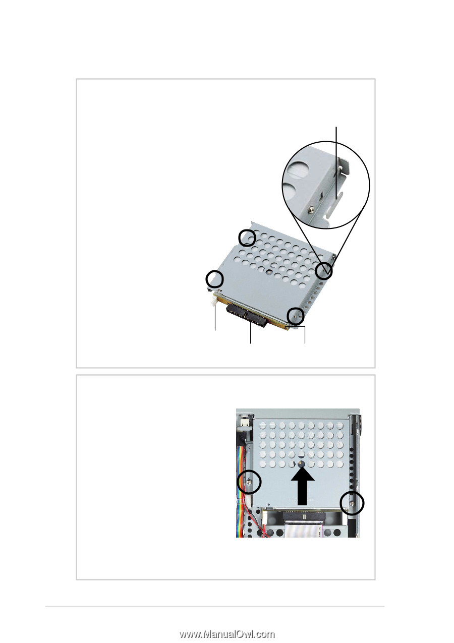
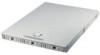
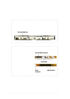
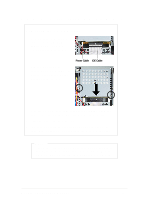
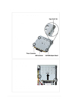
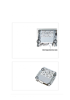
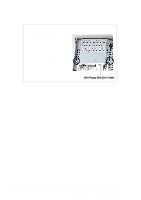
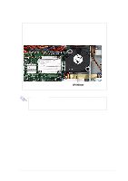
3.1 Remove/Install a CD-ROM Drive Mounting the CD-ROM Drive 1. Attach the CD-ROM adapter board to the rear end of the slim CD-ROM. 2. Place the drive into the drive cage. Take note of the drive cage orientation. The front of the drive should go to the end with the cage guide tab. 3. Secure the drive to the cage using four screws in the areas indicated by circles as shown in the picture. Cage Guide Tab Power Connector IDE Connector CD-ROM Adapter Board Installing the CD-ROM Drive 1. Place the CD-ROM drive on its bay and slide it inward for about an inch (as indicated by the arrow), making sure that the cage guide tab locks in place. 2. Secure the drive cage to the chassis with two screws in the areas indicated by circles. 3. Connect the IDE and power cables to the connectors on the rear of the drive. 30 Chapter 4: Hardware Options
-
 1
1 -
2
-
3
-
4
-
5
-
6
-
7
-
8
-
9
-
10
-
11
-
12
-
13
-
14
-
15
-
16
-
17
-
18
-
19
-
20
-
21
-
22
-
23
-
24
-
 25
25 -
 26
26 -
 27
27 -
 28
28 -
 29
29 -
 30
30 -
 31
31 -
 32
32 -
 33
33 -
 34
34 -
 35
35 -
36
-
37
-
38
-
39
-
40
-
41
-
42
-
43
-
44
 |
 |