Asus AP140R AP140R User Manual English Edition - Page 15
Front Panel Features, 3 Rear Panel Features
 |
View all Asus AP140R manuals
Add to My Manuals
Save this manual to your list of manuals |
Page 15 highlights
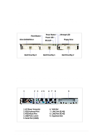
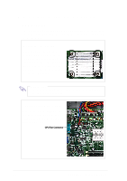
1.2 Front Panel Features The front panel of the server allows easy access to the floppy, CDROM, and hard disk drives. The power button and the system LED indicators are also located on the front panel. Reset Button Slim CD-ROM Drive Power Button Power LED IDE LED Message LED Floppy Drive Hard Drive Bay 0 Hard Drive Bay 1 Hard Drive Bay 2 1.3 Rear Panel Features The server rear panel includes the connectors the system devices and a slot for an expansion card. 1 2 3 45 6 7 8 9 1. AC Power Connector 2. PS/2 Keyboard Port 3. PS/2 Mouse Port 4. USB Ports 1 and 2 5. Serial Port (COM1) 6. VGA Port 7. LAN1 Port (RJ-45) 8. LAN2 Port (RJ-45) 9. Expansion Slot AP140R Server User's Manual 15
-
 1
1 -
2
-
3
-
4
-
5
-
6
-
7
-
8
-
9
-
 10
10 -
 11
11 -
 12
12 -
 13
13 -
 14
14 -
 15
15 -
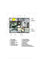 16
16 -
 17
17 -
 18
18 -
 19
19 -
 20
20 -
21
-
22
-
23
-
24
-
25
-
26
-
27
-
28
-
29
-
30
-
31
-
32
-
33
-
34
-
35
-
36
-
37
-
38
-
39
-
40
-
41
-
42
-
43
-
44
 |
 |

AP140R Server User’s Manual
15
1.2 Front Panel Features
The front panel of the server allows easy access to the floppy, CD-
ROM, and hard disk drives. The power button and the system LED
indicators are also located on the front panel.
1.3 Rear Panel Features
The server rear panel includes the connectors the system devices
and a slot for an expansion card.
Hard Drive Bay 0
Slim CD-ROM Drive
IDE LED
Floppy Drive
Power LED
Power Button
Message LED
Reset Button
Hard Drive Bay 1
Hard Drive Bay 2
1. AC Power Connector
2. PS/2 Keyboard Port
3. PS/2 Mouse Port
4. USB Ports 1 and 2
5. Serial Port (COM1)
6.
VGA Port
7.
LAN1 Port (RJ-45)
8.
LAN2 Port (RJ-45)
9.
Expansion Slot
1
2
3
4
5
6
7
8
9