Asus AP1710-I5 AP1710-I5 English Manual
Asus AP1710-I5 Manual
 |
View all Asus AP1710-I5 manuals
Add to My Manuals
Save this manual to your list of manuals |
Asus AP1710-I5 manual content summary:
- Asus AP1710-I5 | AP1710-I5 English Manual - Page 1
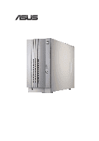
® AP1710-I5 Intel® Xeon Tower/5U Rackmount Server with 533MHz FSB support User's Manual - Asus AP1710-I5 | AP1710-I5 English Manual - Page 2
AS A COMMITMENT BY ASUS. ASUS ASSUMES NO RESPONSIBILITY OR LIABILITY FOR ANY ERRORS OR INACCURACIES THAT MAY APPEAR IN THIS MANUAL, INCLUDING THE PRODUCTS AND SOFTWARE DESCRIBED IN IT. Copyright © 2003 ASUSTeK COMPUTER INC. All Rights Reserved. Product Name: AP1710-I5 Manual Revision: First Edition - Asus AP1710-I5 | AP1710-I5 English Manual - Page 3
44370 Nobel Drive, Fremont, CA 94538, USA +1-510-608-4555 [email protected] Technical Support Support Fax: General Support: Web Site: Support Email: +1-510-608-4555 +1-502-933-8713 www.asus.com [email protected] ASUS COMPUTER GmbH (Germany & Austria) Address: General Fax: General Email: Harkortstr. 25 - Asus AP1710-I5 | AP1710-I5 English Manual - Page 4
radiate radio frequency energy and, if not installed and used in accordance with manufacturer's instructions, may cause harmful interference to radio communications. However, there is no guarantee that . This class B digital apparatus complies with Canadian ICES-003. iv ASUS AP1710-I5 - Asus AP1710-I5 | AP1710-I5 English Manual - Page 5
ii ASUS Contact Information iii FCC/CDC Statements iv Safety Precautions vii Electrical Safety vii Operation Safety vii Introduction About this guide I-1 Audience Processing Unit 2-5 2.4 System Memory 2-9 2.5 Fixed Device Bays 2-12 2.6 Installing a Hard Disk Drive 2-18 User's Manual v - Asus AP1710-I5 | AP1710-I5 English Manual - Page 6
2.7 Screwless Expansion Card Slot 2-23 2.8 Long Card Support Guide 2-24 2.9 RAID Card 2-25 2.10 Hard Drive Blower 2-26 2.11 Chassis Chassis Roller-wheel Installation A-2 Appendix B: Power Modules Redundant Power Modules A-4 Appendix C: Troubleshooting Troubleshooting A-9 vi ASUS AP1710-I5 - Asus AP1710-I5 | AP1710-I5 English Manual - Page 7
• Any mechanical operation on this server must be conducted by certified or experienced engineers. • Before operating the server, carefully read all the manuals included with the server package. • Before using the server, make sure all cables are correctly connected and the power cables are not - Asus AP1710-I5 | AP1710-I5 English Manual - Page 8
type recommended by the manufacturer. Dispose of used batteries according to the manufacturer's instructions. CD-ROM Drive Safety Warning CLASS 1 LASER PRODUCT • Electrical hazard, do not remove chassis cover. • This equipment is to be serviced by a trained personnel only. viii ASUS AP1710-I5 - Asus AP1710-I5 | AP1710-I5 English Manual - Page 9
Introduction About this guide "About This Guide" introduces the contents of this document. This part includes the target audience, chapter description, and conventions used. It also lists other sources of information that are not contained in this manual. User's Manual I-1 - Asus AP1710-I5 | AP1710-I5 English Manual - Page 10
C: Troubleshooting This appendix lists the common problems that you may encounter while using the AP1710-I5 server. It lists the possible causes of the problems and offers solutions. You may refer to this part and try to solve simple problems before calling customer support. I-2 ASUS AP1710-I5 - Asus AP1710-I5 | AP1710-I5 English Manual - Page 11
and for product and software updates. 1. ASUS PRL-DL Motherboard User's Manual This manual contains detailed information about the PRL-DL motherboard. 2. ASUS Websites The ASUS websites worldwide provide updated information on ASUS hardware and softare products. The ASUS websites are listed in the - Asus AP1710-I5 | AP1710-I5 English Manual - Page 12
: 1) ATA133 IDE to Ultra160 SCSI HDD bridge board (max. 6 pieces) 2) ASUS AS-35 5U rackmount rail kit 3) ASUS PXL-S30 U320 LSI 1030 SCSI Card 4) ASUS PXI-G45 Gb LAN Card 5) LSI MegaRAID 320-I single channel RAID card If any of the above items is missing, contact your dealer. I-4 ASUS AP1710-I5 - Asus AP1710-I5 | AP1710-I5 English Manual - Page 13
Chapter 1 System Overview This chapter describes the general features of the AP1710-I5 system server. It includes sections on front panel, rear panel and internal specifications. User's Manual 1-1 - Asus AP1710-I5 | AP1710-I5 English Manual - Page 14
1.1 System Features The ASUS AP1710-I5 server is a stylish server system featuring the ASUS PRL-DL motherboard. The server supports the Intel® Xeon™ processor in a 604-pin socket, and includes the latest I/O, LAN, and video technologies through the chipsets embedded on the motherboard. The - Asus AP1710-I5 | AP1710-I5 English Manual - Page 15
133 Hard Drive Swap Trays Front Door Lock 2 USB Ports For more detailed information of each LED display, refer to "1.5 LED Table" on page 1-6. User's Manual 1-3 - Asus AP1710-I5 | AP1710-I5 English Manual - Page 16
Chassis Lock 6 Full-Length PCI Slots You may secure the chassis lock with an additional padlock or other security device for added server system security. 1-4 ASUS AP1710-I5 - Asus AP1710-I5 | AP1710-I5 English Manual - Page 17
3. 2 x IDE cable 4. 51/4" CD-ROM drive 5. HDD hot swap modules 6. 4 x 64 bit 3V PCI slots 7. CPU sockets 8. Internal 68-pin SCSI cable 9. PCI Long Card support guide 10. 12 cm hot swap module blower 11. PRL-DL motherboard 12. Chassis intrusion sensor User - Asus AP1710-I5 | AP1710-I5 English Manual - Page 18
Table The following table describes the LED display found on the front panel and rear panel of the AP1710-I5 server system. Icon 1 1 2 3 4 LED Display Description Green Drive Status LED Red Bridge in HDD Normal/No incoming event ASMS indicate HW monitor event 1 2 3 4 1-6 ASUS AP1710-I5 - Asus AP1710-I5 | AP1710-I5 English Manual - Page 19
Chapter 2 Hardware Setup This chapter lists the hardware setup procedures that you have to perform when installing system components. User's Manual 2-1 - Asus AP1710-I5 | AP1710-I5 English Manual - Page 20
is held by two large thumb screws. Loosen the screws. 2. Slide the chassis cover for about half an inch. 3. Release the cover from the chassis. 2-2 ASUS AP1710-I5 - Asus AP1710-I5 | AP1710-I5 English Manual - Page 21
guide hooks. 2. Slide the chassis cover for about half an inch towards the front until it fits in place. 3. Tighten the thumb screws. There are six (6) chassis guide hooks located on the upper side and lower side of the chassis cover, make sure all six are aligned properly in place. User's Manual - Asus AP1710-I5 | AP1710-I5 English Manual - Page 22
the motherboard to the chassis. Do not overtighten the screws! Doing so may damage the motherboard. Place this side towards the rear of the chassis 2-4 ASUS AP1710-I5 - Asus AP1710-I5 | AP1710-I5 English Manual - Page 23
performance by allowing higher core frequencies, faster execution of integer instructions, and data transfer rate of up to 4.26GB/s. ® CPU into the socket may bend the pins and severely damage the CPU! The motherboard supports either one or two CPUs. If you are installing only one CPU, you MUST - Asus AP1710-I5 | AP1710-I5 English Manual - Page 24
socket while you push down the socket lever to secure the CPU. The lever clicks on the side tab to indicate that it is locked. 2-6 ASUS AP1710-I5 - Asus AP1710-I5 | AP1710-I5 English Manual - Page 25
are tightened properly. Make sure heatsink with fan assembly is mounted properly on the CPU to avoid burning the CPU and/or CPU socket. User's Manual 2-7 - Asus AP1710-I5 | AP1710-I5 English Manual - Page 26
you wish to install two CPUs, repeat the same steps for CPU socket 2. 6. Use CPUFAN2 connector for the second CPU heatsink and fan assembly cable. 2-8 ASUS AP1710-I5 - Asus AP1710-I5 | AP1710-I5 English Manual - Page 27
twice the throughput of SDR memory. For example, a 200MHz DDR DIMM will support a 100MHz memory bus, and a 266MHz DDR DIMM will support a 133MHz memory bus. DDR Data Transfer Rate 266MHz 200MHz DDR Base Frequency be installed only in a socket specially designed for DDR DIMMs. User's Manual 2-9 - Asus AP1710-I5 | AP1710-I5 English Manual - Page 28
, 2GB (x1) = SDRAM 128MB, 256MB, 512MB, 1GB, 2GB (x1) = SDRAM 128MB, 256MB, 512MB, 1GB, 2GB (x1) = Total System Memory (Max. 4GB) = The system chipset only supports PC1600/2100 registered ECC DIMMs. Make sure to use only the specified DIMM types for stable system operation. 2-10 ASUS AP1710-I5 - Asus AP1710-I5 | AP1710-I5 English Manual - Page 29
a DIMM Follow these steps to remove a DIMM. 1. Simultaneously press the retaining clips outward to unlock the DIMM. 2. Remove the DIMM from the socket. Support the DIMM lightly with your fingers when pressing the retaining clips. The DIMM might get damaged when it flips out with extra force. User - Asus AP1710-I5 | AP1710-I5 English Manual - Page 30
bays are available for installation of additional storage devices like optical disc drives or tape drives. Front door bezel Screwless fixed device bay locks 2-12 ASUS AP1710-I5 - Asus AP1710-I5 | AP1710-I5 English Manual - Page 31
side of the front panel. Take caution in removing the front panel cover. Do not use too much force when installing or removing items. User's Manual 2-13 - Asus AP1710-I5 | AP1710-I5 English Manual - Page 32
the reference point near the "unlocked icon". Unlock Reference points icon Locked icon Knob 4. When released, pull- out the lock and set it aside. 2-14 ASUS AP1710-I5 - Asus AP1710-I5 | AP1710-I5 English Manual - Page 33
door hinges Front Panel plastic bay cover 8. Fasten the four (4) front panel hinges to the slotted chassis holes then close the front panel cover. User's Manual 2-15 - Asus AP1710-I5 | AP1710-I5 English Manual - Page 34
side chassis cover. 3. Pull out and detach the right side chassis cover and set aside. 4. Locate the floppy disk drive cable and power connectors. 2-16 ASUS AP1710-I5 - Asus AP1710-I5 | AP1710-I5 English Manual - Page 35
4.a Carefully detach the floppy disk drive cable. 4.b Carefully detach the floppy disk drive power cable. 5. Pull out the floppy disk drive tray while squeezing the two tabs together. User's Manual Floppy disk drive tray 2-17 - Asus AP1710-I5 | AP1710-I5 English Manual - Page 36
the tray lever outwards. 2. When the tray lever is pulled down, the tray will eject slightly. Pull the tray outwards on the tray lever. 2-18 ASUS AP1710-I5 - Asus AP1710-I5 | AP1710-I5 English Manual - Page 37
middle bracket. Take caution in handling the drive tray, the plastic drive tray rail may break. 3. Replace the rear bracket and fasten with screws. User's Manual 2-19 - Asus AP1710-I5 | AP1710-I5 English Manual - Page 38
to the tray with two (2) round head screws. SCSI-IDE HDD Bridge 2-20 Do not overtighten the screws, the plastic drive tray rails may break. ASUS AP1710-I5 - Asus AP1710-I5 | AP1710-I5 English Manual - Page 39
and qualified hard disk drives listed above. Other hard disk drives manufactured by other vendors may not be suitable for this server system. Visit the ASUS website (www.asus.com) for the latest qualified hard disk drive list. User - Asus AP1710-I5 | AP1710-I5 English Manual - Page 40
. Make sure that the HDD tray is completely in place before you push the handle back to avoid damaging the drive and the tray. 2-22 ASUS AP1710-I5 - Asus AP1710-I5 | AP1710-I5 English Manual - Page 41
2.7 Screwless Expansion Card Slot The AP1710-I5 chassis is designed with a screwless expansion card slot for Personal Computer Interface (PCI) card installation convenience. To add or remove in the slots, then pull the spring lock lever to fasten the expansion cards in place. User's Manual 2-23 - Asus AP1710-I5 | AP1710-I5 English Manual - Page 42
Long Card Support Guide The long card support guide secures that long expansion cards are positioned firmly in place. Make sure the handle of the expansion card is locked in the expansion card guide. To install injury, damage the expansion card or other motherboard components. 2-24 ASUS AP1710-I5 - Asus AP1710-I5 | AP1710-I5 English Manual - Page 43
2.9 SCSI Card The following picture shows the proper cabling of an installed SCSI card. It is recommended that the given SCSI card installation specification and settings are followed for easier handling and maintenance. SCSI Card User's Manual 2-25 - Asus AP1710-I5 | AP1710-I5 English Manual - Page 44
a blower mounted under the hot swap bays.The drive blower status can be monitored through the ASUS® Server Management Software (ASMS) for remote management convenience. 2.10.1 Removing the hard drive blower 2. Pull out the blower housing while squeezing the two tabs together. 2-26 ASUS AP1710-I5 - Asus AP1710-I5 | AP1710-I5 English Manual - Page 45
by a 12-cm chassis fan mounted at the rear panel.The chassis fan status can be monitored remotely through the ASUS® Server Management Software (ASMS). 2.11.1 Removing the 12-cm chassis fan To remove the 12-cm chassis fan, pin to the rear panel. 3. Pull out the 12-cm chassis fan. User's Manual 2-27 - Asus AP1710-I5 | AP1710-I5 English Manual - Page 46
HDD Access cables 11. Front USB Connector 12. 20-pin system panel These are not the names of the connectors. Refer to the motherboard user's manual for detailed information on the motherboard connectors. 2-28 ASUS AP1710-I5 - Asus AP1710-I5 | AP1710-I5 English Manual - Page 47
the current output tipped over the safety limit. HDD blower power cable and connector Power connectors SCSI cable SMBus to power SMBus to motherboard User's Manual 2-29 - Asus AP1710-I5 | AP1710-I5 English Manual - Page 48
ID = 5 (Disk Drive 6) B. SCSI Backplane Backside HD activity LED HD status LED Refer to "1.5 LED Table" on page 1-6, for detailed SCSI Backplane LED display descriptions. ASUS AP1710-I5 - Asus AP1710-I5 | AP1710-I5 English Manual - Page 49
Appendix A Chassis Roller-wheel This appendix contains the installation procedure for the optional chassis roller-wheel units for the AP1710-I5 server system. User's Manual A-1 - Asus AP1710-I5 | AP1710-I5 English Manual - Page 50
Chassis Roller-wheel Installation The AP1710-I5 comes with an optional roller-wheel for the chassis for server transport convenience. Follow these easy steps to locks All the chassis roller-wheels can be locked individually with its built-in chassis-roller wheel brake locks. A-2 ASUS AP1710-I5 - Asus AP1710-I5 | AP1710-I5 English Manual - Page 51
Appendix B Power Modules This appendix contains detailed hardware operation and specifications of the AP1710-I5 redundant power modules. User's Manual A-3 - Asus AP1710-I5 | AP1710-I5 English Manual - Page 52
, follow these steps. 1. Remove the screw. 2. Pull on the handle while pressing down the rubber lever. Redundant Power Housing Lever Screw 500W Redundant Power Module A-4 ASUS AP1710-I5 - Asus AP1710-I5 | AP1710-I5 English Manual - Page 53
-p 120mVp-p 50mVp-p Max (A) 24.5 17.5 25.0 0.2 2.0 Max. Load (W) 81.6 87.5 300 2.4 10 Over-Voltage Protection (OVP) Voltage +3.33V +5V Min (V) 3.7 5.5 +12V 12.9 Max (V) 4.5 6.5 14.2 User's Manual A-5 - Asus AP1710-I5 | AP1710-I5 English Manual - Page 54
and motherboard. 3. Remove the six (6) chassis bar screws and release chassis bar. 4. Remove the two (2) right-side chassis cover screws to release right-side cover. A-6 ASUS AP1710-I5 - Asus AP1710-I5 | AP1710-I5 English Manual - Page 55
screws. 6. Remove the six (6) power case top screws. Make sure the power case is well supported or held when releasing the power case screws. The power case may accidentally detach and cause damage -ROM 8. Floppy drive 9. SMBUS cable for power supply Power case cable connectors User's Manual A-7 - Asus AP1710-I5 | AP1710-I5 English Manual - Page 56
A-8 ASUS AP1710-I5 - Asus AP1710-I5 | AP1710-I5 English Manual - Page 57
C Troubleshooting This appendix lists the common problems that you may encounter while using the AP1710-I5 server system. It lists possible causes of the problems and offers solutions. You may refer to this part and try to solve simple problems before calling customer support. User's Manual A-9 - Asus AP1710-I5 | AP1710-I5 English Manual - Page 58
on the system or the components. These problems only requires simple troubleshooting actions that you can perform by yourself. Problem Action The power LED on the server and correct DIMMs the system supports. 2. Make sure that the DIMMs are properly installed on the sockets. A-10 ASUS AP1710-I5 - Asus AP1710-I5 | AP1710-I5 English Manual - Page 59
Problem Action The system continuously beeps after it was turned on 1. Check the memory modules and make sure you installed the correct DIMMs the system supports. 2. Make sure that the DIMMs are properly installed have installed the network drivers from the system support CD. User's Manual A-11 - Asus AP1710-I5 | AP1710-I5 English Manual - Page 60
A-12 ASUS AP1710-I5
-
 1
1 -
 2
2 -
 3
3 -
 4
4 -
 5
5 -
 6
6 -
 7
7 -
8
-
9
-
10
-
11
-
12
-
13
-
14
-
15
-
16
-
17
-
18
-
19
-
20
-
21
-
22
-
23
-
24
-
25
-
26
-
27
-
28
-
29
-
30
-
31
-
32
-
33
-
34
-
35
-
36
-
37
-
38
-
39
-
40
-
41
-
42
-
43
-
44
-
45
-
46
-
47
-
48
-
49
-
50
-
51
-
52
-
53
-
54
-
55
-
56
-
57
-
58
-
59
-
60
 |
 |

Intel
®
Xeon Tower/5U Rackmount Server
®
AP1710-I5
User’s Manual
with 533MHz FSB support