Asus AP1710-I5 AP1710-I5 English Manual - Page 46
Connecting Cables
 |
View all Asus AP1710-I5 manuals
Add to My Manuals
Save this manual to your list of manuals |
Page 46 highlights
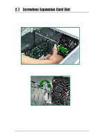
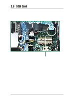
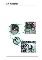
2.12 Connecting Cables Most of the cables in the server are already pre-connected to their respective connectors. The following illustrates the corresponding components that are connected to these connectors. 2 3 10 4 5 9 1 7 6 12 8 11 1. Chassis fan (SYSFAN3) 2. 8-pin 12V AUX Power 3. 24-pin ATX Power 4. Primary IDE 5. Secondary IDE 6. Chassis intrusion 7. Floppy Disk Drive 8. SMBus Panel to backplane 9. SCSI Controller 10. Two IDE HDD Access cables 11. Front USB Connector 12. 20-pin system panel These are not the names of the connectors. Refer to the motherboard user's manual for detailed information on the motherboard connectors. 2-28 ASUS AP1710-I5
-
 1
1 -
2
-
3
-
4
-
5
-
6
-
7
-
8
-
9
-
10
-
11
-
12
-
13
-
14
-
15
-
16
-
17
-
18
-
19
-
20
-
21
-
22
-
23
-
24
-
25
-
26
-
27
-
28
-
29
-
30
-
31
-
32
-
33
-
34
-
35
-
36
-
37
-
38
-
39
-
40
-
 41
41 -
 42
42 -
 43
43 -
 44
44 -
 45
45 -
 46
46 -
 47
47 -
 48
48 -
 49
49 -
 50
50 -
 51
51 -
52
-
53
-
54
-
55
-
56
-
57
-
58
-
59
-
60
 |
 |

2-28
ASUS AP1710-I5
2.12
Connecting Cables
Most of the cables in the server are already pre-connected to their
respective connectors. The following illustrates the corresponding
components that are connected to these connectors.
1. Chassis fan (SYSFAN3)
2. 8-pin 12V AUX Power
3. 24-pin ATX Power
4. Primary IDE
5. Secondary IDE
6. Chassis intrusion
7. Floppy Disk Drive
8. SMBus Panel to backplane
9. SCSI Controller
10. Two IDE HDD Access cables
11. Front USB Connector
12. 20-pin system panel
These are not the names of the connectors. Refer to the motherboard
user’s manual for detailed information on the motherboard connectors.
2
3
10
9
6
1
12
8
11
7
5
4