Asus AP1710-I5 AP1710-I5 English Manual - Page 38
Secure the SCSI-IDE HDD
 |
View all Asus AP1710-I5 manuals
Add to My Manuals
Save this manual to your list of manuals |
Page 38 highlights
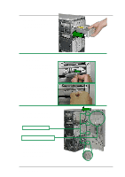
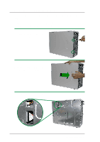
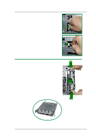
4. Prepare hard disk drive. Carefully insert the SCSI-IDE HDD bridge to the hard drive's 40-1 pin IDE connector and 4-pin power connector. Make sure the SCSI-IDE HDD bridge is slotted properly and placed firmly in place. Take caution when assembling or disassembling the bridge board to the hard disk drive. The SCSI-IDE HDD bridge board may break if handled improperly. 5. Carefully place the hard disk drive into the drive tray. Align the hard drive's four (4) screw holes with the hard drive tray rails. Secure hard drive with four (4) round head screws. 6. Secure the SCSI-IDE HDD Bridge to the tray with two (2) round head screws. SCSI-IDE HDD Bridge 2-20 Do not overtighten the screws, the plastic drive tray rails may break. ASUS AP1710-I5
-
 1
1 -
2
-
3
-
4
-
5
-
6
-
7
-
8
-
9
-
10
-
11
-
12
-
13
-
14
-
15
-
16
-
17
-
18
-
19
-
20
-
21
-
22
-
23
-
24
-
25
-
26
-
27
-
28
-
29
-
30
-
31
-
32
-
 33
33 -
 34
34 -
 35
35 -
 36
36 -
 37
37 -
 38
38 -
 39
39 -
 40
40 -
 41
41 -
 42
42 -
 43
43 -
44
-
45
-
46
-
47
-
48
-
49
-
50
-
51
-
52
-
53
-
54
-
55
-
56
-
57
-
58
-
59
-
60
 |
 |

2-20
ASUS AP1710-I5
SCSI-IDE HDD Bridge
4. Prepare hard disk drive.
Carefully insert the SCSI-IDE
HDD bridge to the hard drive’s
40-1 pin IDE connector and 4-pin
power connector. Make sure the
SCSI-IDE HDD bridge is slotted
properly and placed firmly in
place.
5. Carefully place the hard disk
drive into the drive tray. Align the
hard drive’s
four (4) screw holes
with the hard drive tray rails.
Secure hard drive with four (4)
round head screws.
Do not overtighten the screws, the plastic drive tray rails may break.
6. Secure the SCSI-IDE HDD
Bridge to the tray with two (2)
round head screws.
Take caution when assembling or
disassembling the bridge board to the
hard disk drive. The SCSI-IDE HDD
bridge board may break if handled
improperly.