Asus AT5IONT-I AT5IONT-I User's manual - Page 11
Motherboard overview - atom d525
 |
View all Asus AT5IONT-I manuals
Add to My Manuals
Save this manual to your list of manuals |
Page 11 highlights
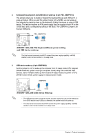
1.2 1.2.1 Motherboard overview Motherboard layout ASUS AT5IONT-I Series motherboards include AT5IONT-I and AT5IONT-I DELUXE two models. The layout varies with models. The layout illustrations in this user guide are for AT5IONT-I DELUXE only. Ensure that you install the motherboard into the chassis in the correct orientation. The edge with external ports goes to the rear part of the chassis. 1 2 3 17.1cm(6.75in) CHA_FAN DDR3 SO-DIMM_A2 (64bit, 204-pin module) PWR_FAN CPU_FAN DC_PWR/ WiFi antenna KBMS 3 PS2_USBPW1-4 Lithium Cell CMOS Power DDR3 SO-DIMM_A1 (64bit, 204-pin module) SPDIFO_HDMI Place this side towards the rear of the chassis. Super NVIDIA® 4 I/O ION2010 Intel® 5 Atom D525 DVI JMB 360 17.1cm(6.75in) SATA_PWR1 ESATA Intel® _USB34 _BT RTL 8112 ICS NM10 6 9LRS954 7 F_PANEL SPEAKER USBPW56 LAN1_USB3.0_12 NEC USB3.0 AUDIO ALC 887 P17C9X20 USB56 SATA1 SATA2 CLRTC 8 8Mb BIOS AAFP PCIEX4_1 SB_PWR AT5IONT-I DELUXE 13 12 11 10 9 Place four screws into the holes indicated by circles to secure the motherboard to the chassis. DO NOT overtighten the screws! Doing so can damage the motherboard. ASUS AT5IONT-I Series 1-2
-
 1
1 -
2
-
3
-
4
-
5
-
 6
6 -
 7
7 -
 8
8 -
 9
9 -
 10
10 -
 11
11 -
 12
12 -
 13
13 -
 14
14 -
 15
15 -
 16
16 -
17
-
18
-
19
-
20
-
21
-
22
-
23
-
24
-
25
-
26
-
27
-
28
-
29
-
30
-
31
-
32
-
33
-
34
-
35
-
36
-
37
-
38
-
39
-
40
-
41
-
42
-
43
-
44
-
45
-
46
-
47
 |
 |
