Asus AT5IONT-I AT5IONT-I User's manual - Page 12
Central Processing Unit CPU, System memory - what memory
 |
View all Asus AT5IONT-I manuals
Add to My Manuals
Save this manual to your list of manuals |
Page 12 highlights
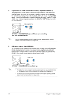
1.2.2 Layout contents Connectors/Jumpers/LED Page Connectors/Jumpers/LED Page 1. Keyboard/mouse power and USB device wake-up (3-pin PS2_USBPW1-4) 1-7 8. Clear RTC RAM (3-pin CLRTC) 1-6 2. Atom D525 processor 1-3 9. Internal speaker connector (4-pin SPEAKER) 1-12 3. CPU, power, and chassis fan connectors (3-pin CPU_FAN, 3-pin PWR_FAN, 3-pin CHA_FAN) 1-11 10. Serial ATA connectors (7-pin SATA1/2) 1-10 4. DDR3 SO-DIMM slots 1-3 11. USB connector (10-1 pin USB56) 1-11 5. USB device wake-up (3-pin USBPW56) 1-7 12. Standby power LED (SB_PWR) 1-1 6. SATA power connector (4-pin SATA_PWR1) 1-13 13. Front panel audio connector (10-1 pin AAFP) 1-12 7. System panel connector (10-1 pin F_PANEL) 1-13 1.3 Central Processing Unit (CPU) The motherboard comes with an onboard Dual-Core Intel® Atom™ D525 processor and a specially designed CPU heatsink. D525 AT5IONT-I DELUXE AT5IONT-I DELUXE CPU - Atom D525 1.4 System memory 1.4.1 Overview This motherboard comes with two Double Data Rate 3 (DDR3) Small Outline Dual Inline Memory Modules (SO-DIMM) sockets. The figure illustrates the location of the DDR3 DIMM sockets: DIMM_A1 DIMM_A2 AT5IONT-I DELUXE AT5IONT-I DELUXE 204-pin DDR3 SO-DIMM sockets 1-3 Chapter 1: Product introduction
-
 1
1 -
2
-
3
-
4
-
5
-
6
-
 7
7 -
 8
8 -
 9
9 -
 10
10 -
 11
11 -
 12
12 -
 13
13 -
 14
14 -
 15
15 -
 16
16 -
 17
17 -
18
-
19
-
20
-
21
-
22
-
23
-
24
-
25
-
26
-
27
-
28
-
29
-
30
-
31
-
32
-
33
-
34
-
35
-
36
-
37
-
38
-
39
-
40
-
41
-
42
-
43
-
44
-
45
-
46
-
47
 |
 |
