Asus AT5IONT-I AT5IONT-I User's manual - Page 22
SATA power connectors 4-pin SATA_PWR1 for AT5IONT-I DELUXE only - sleep
 |
View all Asus AT5IONT-I manuals
Add to My Manuals
Save this manual to your list of manuals |
Page 22 highlights
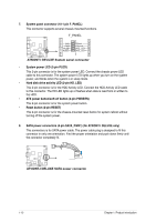
7. System panel connector (10-1 pin F_PANEL) This connector supports several chassis-mounted functions. F_PANEL PWR LED PWR BTN PIN 1 HD_LED RESET GND PWR PLEDPLED+ Reset Ground IDE_LEDIDE_LED+ AT5IONT-I DELUXE AT5IONT-I DELUXE System panel connector • System power LED (2-pin PLED) This 2-pin connector is for the system power LED. Connect the chassis power LED cable to this connector. The system power LED lights up when you turn on the system power, and blinks when the system is in sleep mode. • Hard disk drive activity LED (2-pin HD_LED) This 2-pin connector is for the HDD Activity LED. Connect the HDD Activity LED cable to this connector. The HD LED lights up or flashes when data is read from or written to the HDD. • ATX power button/soft-off button (2-pin PWRBTN) This 2-pin connector is for the system power button. • Reset button (2-pin RESET) This 2-pin connector is for the chassis-mounted reset button for system reboot without turning off the system power. 8. SATA power connectors (4-pin SATA_PWR1) (for AT5IONT-I DELUXE only) This connectors is for SATA power cable. The power cable plug is designed to fit this connector in only one orientation. Find the proper orientation and push down firmly until the connector completely fit. AT5IONT-I DELUXE AT5IONT-I DELUXE SATA power connector 1-13 Chapter 1: Product introduction
-
 1
1 -
2
-
3
-
4
-
5
-
6
-
7
-
8
-
9
-
10
-
11
-
12
-
13
-
14
-
15
-
16
-
 17
17 -
 18
18 -
 19
19 -
 20
20 -
 21
21 -
 22
22 -
 23
23 -
 24
24 -
 25
25 -
 26
26 -
 27
27 -
28
-
29
-
30
-
31
-
32
-
33
-
34
-
35
-
36
-
37
-
38
-
39
-
40
-
41
-
42
-
43
-
44
-
45
-
46
-
47
 |
 |
