Asus CUSL2 CUSL2 User Manual - Page 40
ASUS CUSL2 User's Manual, LCD-TV Headers 18-pin, 18-1 pin LCDTV, USB Headers 5-pin USB2, 10-1 pin
 |
View all Asus CUSL2 manuals
Add to My Manuals
Save this manual to your list of manuals |
Page 40 highlights
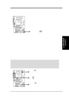
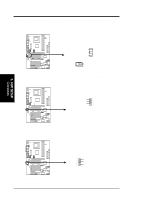
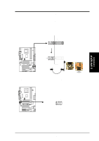
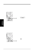
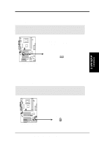
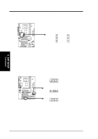
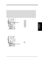
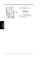
3. HARDWARE SETUP 22) LCD-TV Headers (18-pin, 18-1 pin LCDTV) These headers require an optional LCD module for LCD output or a TV-out module for TV output. ® CUSL2 CUSL2 LCD-TV Headers LCDTV 1 23) USB Headers (5-pin USB2, 10-1 pin USB47, 10-1 pin USB56) If the USB Ports on the back panels are inadequate, three USB headers are available for five additional USB ports. Connect the 5-pin ribbon cable from the provided 3-port USB connector set to the midboard 5-pin USB header and the 10-1 pin ribbon cable to one of the two midboard 10-1 pin USB headers and mount the USB connector set to an open slot on your chassis. USB47 10 5 6 1: USB Power 6: USB Power 2: USBP4- 7: USBP7- 1 3: USBP4+ 4: GND 8: USBP7+ 9: GND 5: NC USBPWR USBP2USBP2+ GND ® CUSL2 CUSL2 USB Headers USB2 1 USB56 10 5 1: USB Power 6: USB Power 6 2: USBP5- 3: USBP5+ 7: USBP6- 8: USBP6+ 1 4: GND 5: NC 9: GND 3. H/W SETUP Connectors 40 ASUS CUSL2 User's Manual
-
 1
1 -
2
-
3
-
4
-
5
-
6
-
7
-
8
-
9
-
10
-
11
-
12
-
13
-
14
-
15
-
16
-
17
-
18
-
19
-
20
-
21
-
22
-
23
-
24
-
25
-
26
-
27
-
28
-
29
-
30
-
31
-
32
-
33
-
34
-
 35
35 -
 36
36 -
 37
37 -
 38
38 -
 39
39 -
 40
40 -
 41
41 -
 42
42 -
 43
43 -
 44
44 -
 45
45 -
46
-
47
-
48
-
49
-
50
-
51
-
52
-
53
-
54
-
55
-
56
-
57
-
58
-
59
-
60
-
61
-
62
-
63
-
64
-
65
-
66
-
67
-
68
-
69
-
70
-
71
-
72
-
73
-
74
-
75
-
76
-
77
-
78
-
79
-
80
-
81
-
82
-
83
-
84
-
85
-
86
-
87
-
88
-
89
-
90
-
91
-
92
-
93
-
94
-
95
-
96
-
97
-
98
-
99
-
100
-
101
-
102
-
103
-
104
-
105
-
106
-
107
-
108
-
109
-
110
-
111
-
112
-
113
-
114
-
115
-
116
-
117
-
118
-
119
-
120
-
121
-
122
-
123
-
124
-
125
-
126
-
127
-
128
 |
 |
