Asus CUSL2 CUSL2 User Manual - Page 41
ASUS CUSL2 User's Manual, ATX Power Supply Connector, pin block ATXPWR, Power Supply Thermal Sensor
 |
View all Asus CUSL2 manuals
Add to My Manuals
Save this manual to your list of manuals |
Page 41 highlights
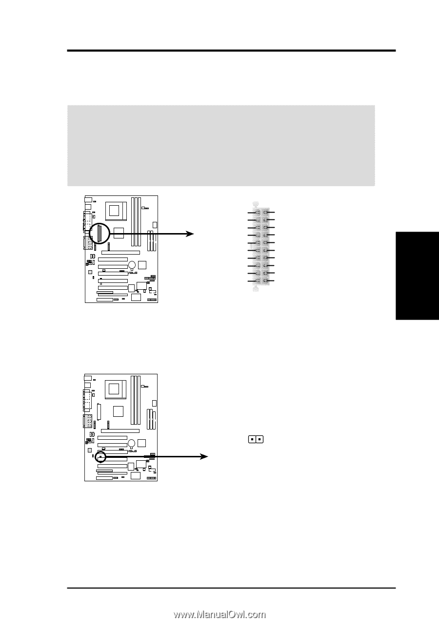
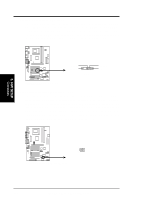
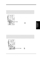
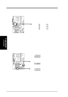
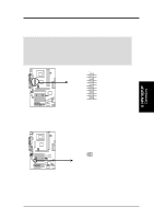
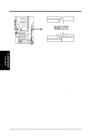
3. H/W SETUP Connectors 3. HARDWARE SETUP 24) ATX Power Supply Connector (20-pin block ATXPWR) This connector connects to an ATX power supply. The plug from the power supply will only insert in one orientation because of the different hole sizes. Find the proper orientation and push down firmly making sure that the pins are aligned. IMPORTANT: Make sure that your ATX power supply (minimum recommended wattage: 200 watts; 235W for a fully-configured system) can supply at least 20 amperes on the +5-volt lead and at least 10mA (750mA recommended) on the +5volt standby lead (+5VSB). Your system may become unstable/unreliable and may experience difficulty in powering up if your power supply is inadequate. For WakeOn-LAN support, your ATX power supply must supply at least 750mA +5VSB. ® CUSL2 +3.3 Volts -12.0 Volts Ground Power Supply On Ground Ground Ground -5.0 Volts +5.0 Volts +5.0 Volts CUSL2 ATX Power Connector +3.3 Volts +3.3 Volts Ground +5.0 Volts Ground +5.0 Volts Ground Power Good +5V Standby +12.0 Volts 25) Power Supply Thermal Sensor Connector (2-pin JTPWR) If you have a power supply with thermal monitoring, connect its thermal sensor cable to this connector. JTPWR ® CUSL2 CUSL2 Thermal Sensor Connector Power Supply Thermal Sensor ASUS CUSL2 User's Manual 41
-
 1
1 -
2
-
3
-
4
-
5
-
6
-
7
-
8
-
9
-
10
-
11
-
12
-
13
-
14
-
15
-
16
-
17
-
18
-
19
-
20
-
21
-
22
-
23
-
24
-
25
-
26
-
27
-
28
-
29
-
30
-
31
-
32
-
33
-
34
-
35
-
 36
36 -
 37
37 -
 38
38 -
 39
39 -
 40
40 -
 41
41 -
 42
42 -
 43
43 -
 44
44 -
 45
45 -
 46
46 -
47
-
48
-
49
-
50
-
51
-
52
-
53
-
54
-
55
-
56
-
57
-
58
-
59
-
60
-
61
-
62
-
63
-
64
-
65
-
66
-
67
-
68
-
69
-
70
-
71
-
72
-
73
-
74
-
75
-
76
-
77
-
78
-
79
-
80
-
81
-
82
-
83
-
84
-
85
-
86
-
87
-
88
-
89
-
90
-
91
-
92
-
93
-
94
-
95
-
96
-
97
-
98
-
99
-
100
-
101
-
102
-
103
-
104
-
105
-
106
-
107
-
108
-
109
-
110
-
111
-
112
-
113
-
114
-
115
-
116
-
117
-
118
-
119
-
120
-
121
-
122
-
123
-
124
-
125
-
126
-
127
-
128
 |
 |