Asus KN97-X User Manual - Page 23
Installation
 |
View all Asus KN97-X manuals
Add to My Manuals
Save this manual to your list of manuals |
Page 23 highlights
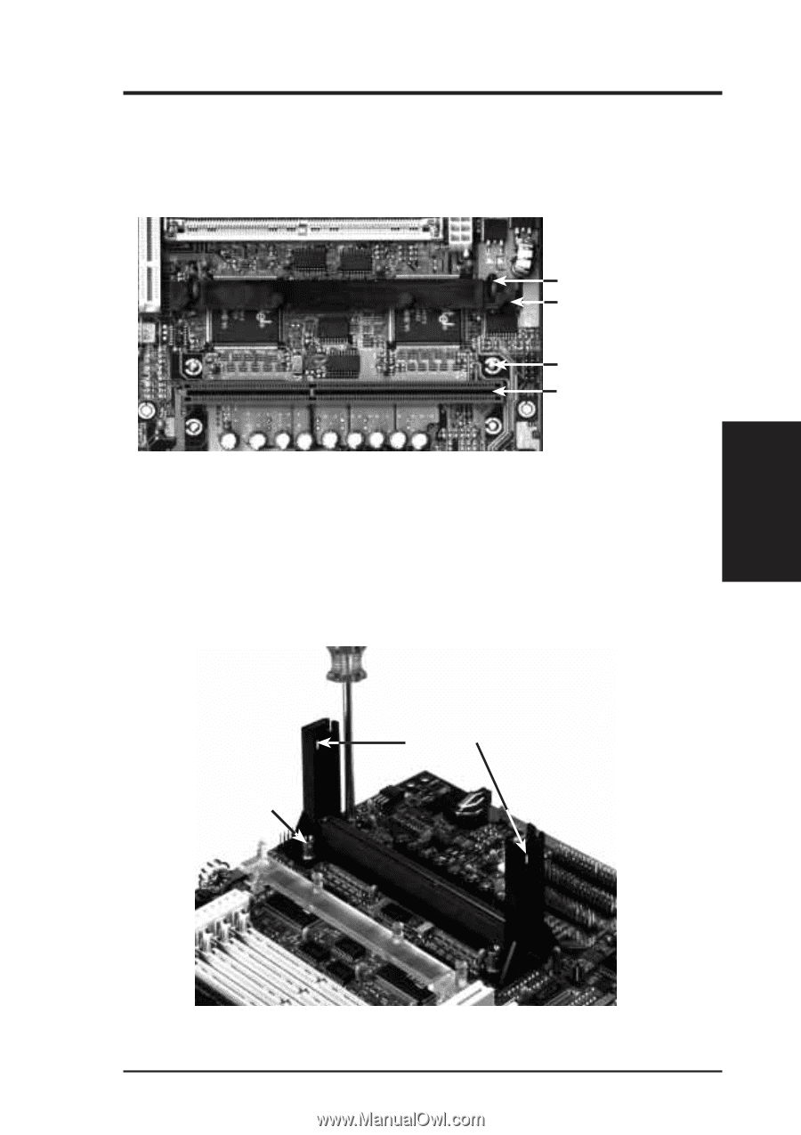
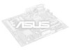
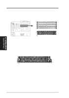
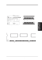
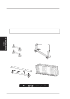
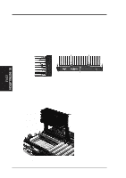
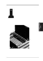
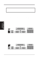
III. INSTALLATION (CPU) III. INSTALLATION From the Manufacturer: Four screws should be showing next to each corner of the SEC Slot using two Attach Mount Bridges from the underside of the motherboard. A bottom Heatsink Support Base should be mounted over the two chipsets in front of the slot. Heatsink Support Base Pin (5&6) Support Base (7) Screw from Mount Bridge (1&2) Pentium II processor SEC slot View of the KN97-X Motherboard from the Manufacturer Installing the Pentium II Processor: 1. Mount the Pentium II Retention Mechanism: Place the Retention Mecha- nism over the SEC Slot with the Retainer's Lock Holes toward the motherboard's memory slots and screw the Captive Nuts using a Phillips or flat head screw driver. WARNING: Excessive torque may damage your motherboard. Tighten captive nuts to no more than 6±1 inch/pound. (3) Captive Nut Lock Holes Retention Mechanism in place and Captive Nut being tightened ASUS KN97-X User's Manual 23
-
 1
1 -
2
-
3
-
4
-
5
-
6
-
7
-
8
-
9
-
10
-
11
-
12
-
13
-
14
-
15
-
16
-
17
-
 18
18 -
 19
19 -
 20
20 -
 21
21 -
 22
22 -
 23
23 -
 24
24 -
 25
25 -
 26
26 -
 27
27 -
 28
28 -
29
-
30
-
31
-
32
-
33
-
34
-
35
-
36
-
37
-
38
-
39
-
40
-
41
-
42
-
43
-
44
-
45
-
46
-
47
-
48
-
49
-
50
-
51
-
52
-
53
-
54
-
55
-
56
-
57
-
58
-
59
-
60
-
61
-
62
-
63
-
64
 |
 |