Asus KN97-X User Manual - Page 30
Universal Serial BUS Ports 1 & 2 Two 4-pin Female Sockets
 |
View all Asus KN97-X manuals
Add to My Manuals
Save this manual to your list of manuals |
Page 30 highlights
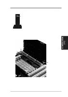
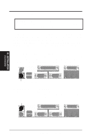
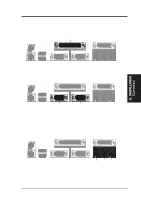
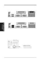
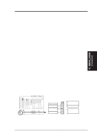
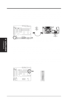
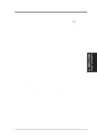
R III. INSTALLATION (Connectors) III. INSTALLATION 6. Joystick/Midi Connector (15-pin Female) (with optional onboard Audio) You may connect game joysticks or game pads to this connector for playing games. Connect Midi devices for playing or editing audio. Joystick/Midi (15-pin Female) 7. Universal Serial BUS Ports 1 & 2 (Two 4-pin Female Sockets) Two USB ports are available for connecting USB devices. USB 1 Univeral Serial Bus (USB) 2 8. Floppy drive connector (34-pin block ) This connector supports the provided floppy drive ribbon cable. After connecting the single end to the board, connect the two plugs on the other end to the floppy drives. (Pin 5 is removed to prevent inserting in the wrong orientation when using ribbon cables with pin 5 plugged). Floppy Drive Connector NOTE: Connect the Red stripe to Pin 1 Floppy Drive Connector Pin 1 30 ASUS KN97-X User's Manual
-
 1
1 -
2
-
3
-
4
-
5
-
6
-
7
-
8
-
9
-
10
-
11
-
12
-
13
-
14
-
15
-
16
-
17
-
18
-
19
-
20
-
21
-
22
-
23
-
24
-
 25
25 -
 26
26 -
 27
27 -
 28
28 -
 29
29 -
 30
30 -
 31
31 -
 32
32 -
 33
33 -
 34
34 -
 35
35 -
36
-
37
-
38
-
39
-
40
-
41
-
42
-
43
-
44
-
45
-
46
-
47
-
48
-
49
-
50
-
51
-
52
-
53
-
54
-
55
-
56
-
57
-
58
-
59
-
60
-
61
-
62
-
63
-
64
 |
 |
