Asus M4A785G HTPC RC User Manual - Page 33
Connectors - universe
 |
View all Asus M4A785G HTPC RC manuals
Add to My Manuals
Save this manual to your list of manuals |
Page 33 highlights
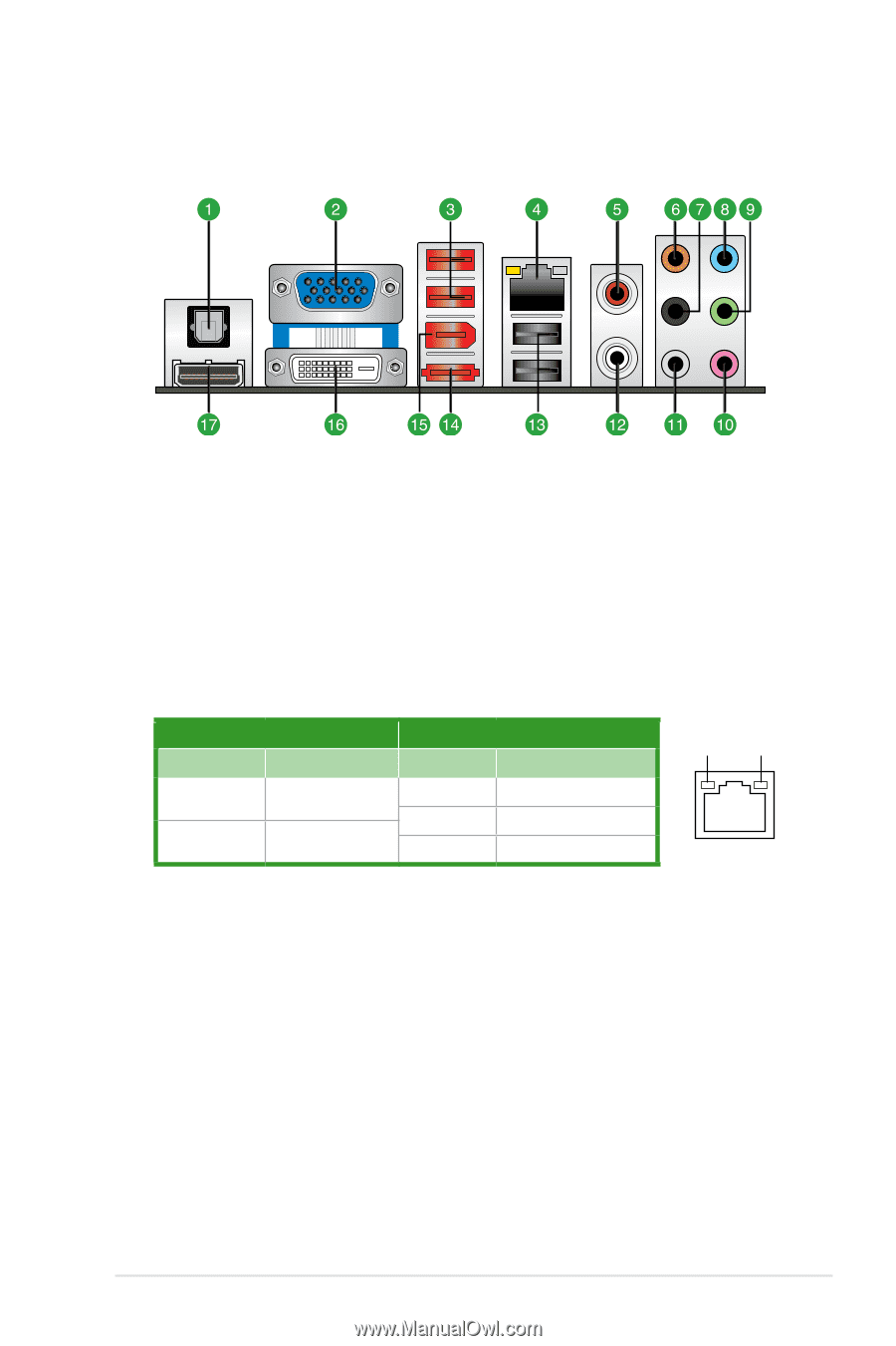
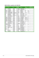
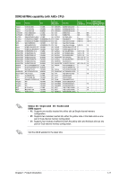
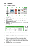
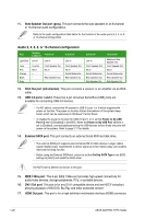
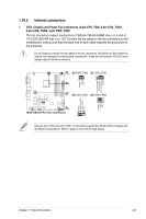
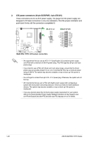
1.10 1.10.1 Connectors Rear panel connectors 1. Optical S/PDIF Out port. This port connects an external audio output device via an optical S/PDIF cable. 2. Video Graphics Adapter (VGA) port This 15-pin port is for a VGA monitor or other VGA-compatible devices. 3. USB 2.0 ports 3 and 4. These two 4-pin Universal Serial Bus (USB) ports are available for connecting USB 2.0 devices. 4. LAN (RJ-45) port. This port allows Gigabit connection to a Local Area Network (LAN) through a network hub. LAN port LED indications Activity Link LED Status Description OFF No link BLINKING Data activity Speed LED Status OFF ORANGE GREEN Description 10 Mbps connection 100 Mbps connection 1 Gbps connection ACT/LINK SPEED LED LED LAN port 5. RCA Out port (right-channel). This port connects a receiver or an amplifier via an RCA cable. 6. Center/Subwoofer port (orange). This port connects the center/subwoofer speakers. 7. Rear Speaker Out port (black). This port connects the rear speakers in a 4-channel, 6-channel, 8-channel, or 10-channel audio configuration. 8. Line In port/Side Speaker Out port (light blue). This port connects the tape, CD, DVD player, or other audio sources in an 8-channel audio configuration. In an 10-channel audio configuration, this port connects the additional side speakers. 9. Line Out port (lime). This port connects a headphone or a speaker. In 4-channel, 6-channel, 8-channel, and 10-channel configuration, the function of this port becomes Front Speaker Out. 10. Microphone port (pink). This port connects a microphone. Chapter 1: Product introduction 1-21
-
 1
1 -
2
-
3
-
4
-
5
-
6
-
7
-
8
-
9
-
10
-
11
-
12
-
13
-
14
-
15
-
16
-
17
-
18
-
19
-
20
-
21
-
22
-
23
-
24
-
25
-
26
-
27
-
 28
28 -
 29
29 -
 30
30 -
 31
31 -
 32
32 -
 33
33 -
 34
34 -
 35
35 -
 36
36 -
 37
37 -
 38
38 -
39
-
40
-
41
-
42
-
43
-
44
-
45
-
46
-
47
-
48
-
49
-
50
-
51
-
52
-
53
-
54
-
55
-
56
-
57
-
58
-
59
-
60
-
61
-
62
-
63
-
64
-
65
-
66
-
67
-
68
-
69
-
70
-
71
-
72
 |
 |