Asus P2B-LS P2B-LS User Manual - Page 10
Iii. Installation - p2b s bios
 |
View all Asus P2B-LS manuals
Add to My Manuals
Save this manual to your list of manuals |
Page 10 highlights
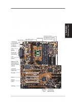
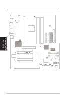
III. INSTALLATION ASUS P2B-L/P2B-S/P2B-LS Motherboard Layout DIMM Socket 0 (64/72 bit, 168 pin module) DIMM Socket 1 (64/72 bit, 168 pin module) DIMM Socket 2 (64/72 bit, 168 pin module) DIMM Socket 3 (64/72 bit, 168 pin module) Parallel Port ATX Power Connector Single Edge Contact CPU Slot PS/2 Power Supply Fan Mouse (top port) Keyboard (bottom port) USB 1 (top port) USB 2 (bottom port) USB KBPWR COM 1 TRCPU CPU_FAN Intel 440BX AGPset FS2 FS1 BUS Freq. FS0 68 34 34 68 COM 2 RJ-45 FLOPPY LAN Activity LED Connector 35 1 35 1 50-Pin SCSI 1 1 68-Pin Wide SCSI 68-Pin Ultra2 SCSI Intel 82558 Ethernet LAN Controller Accelerated Graphics Port PCI Slot 4 SBLINK PCI Slot 3 LAN_EN R Multi-I/O PCI Slot 2 Hardware Monitor PCI Slot 1 ISA Slot 1 ISA Slot 2 SCSI_EN Adaptec SCSI Chipset Adaptec AIC-3860 Chipset SECONDARY IDE 1 PRIMARY IDE Intel PIIX4E Chipset CLRTC 1 Freq. Ratio ASUS A97127F Chipset BF3 BF2 BF1 BF0 BIOS Power (CR2032 3V Lithium Cell) SCSILED CHASSIS WOL_CON EXTBATT 2Mbit Flash EEPROM (Programmable BIOS) CHA_FAN PANEL IDELED Combine IR Speaker NOTE: Greyed components are optional at the time of purchase. III. INSTALLATION Board Layout 10 ASUS P2B-L/P2B-S/P2B-LS User's Manual
-
 1
1 -
2
-
3
-
4
-
 5
5 -
 6
6 -
 7
7 -
 8
8 -
 9
9 -
 10
10 -
 11
11 -
 12
12 -
 13
13 -
 14
14 -
 15
15 -
16
-
17
-
18
-
19
-
20
-
21
-
22
-
23
-
24
-
25
-
26
-
27
-
28
-
29
-
30
-
31
-
32
-
33
-
34
-
35
-
36
-
37
-
38
-
39
-
40
-
41
-
42
-
43
-
44
-
45
-
46
-
47
-
48
-
49
-
50
-
51
-
52
-
53
-
54
-
55
-
56
-
57
-
58
-
59
-
60
-
61
-
62
-
63
-
64
-
65
-
66
-
67
-
68
-
69
-
70
-
71
-
72
-
73
-
74
-
75
-
76
-
77
-
78
-
79
-
80
-
81
-
82
-
83
-
84
-
85
-
86
-
87
-
88
 |
 |
