Asus P2B-LS P2B-LS User Manual - Page 28
Installation
 |
View all Asus P2B-LS manuals
Add to My Manuals
Save this manual to your list of manuals |
Page 28 highlights
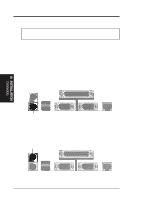
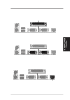
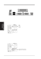
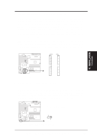
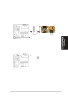
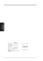
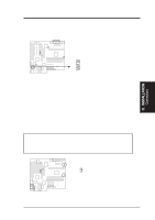
III. INSTALLATION 6. Universal Serial BUS Ports 1 & 2 (Two 4-pin Female) Two USB ports are available for connecting USB devices. USB 1 USB 2 P2B-L/S/LS Universal Serial Bus (USB) 7. LAN Condition Connector (6-pin A) (optional/reserved) This connector supports the optional network condition connector module. This module mounts to system cases that support this feature. Link LED Connector Activity LED Connector Speed LED Connector R R III. INSTALLATION Connectors P2B-L/S/LS Network Condition LED Connectors 8. Floppy Disk Drive Connector (34-1pin FLOPPY) This connector supports the provided floppy disk drive ribbon cable. After connecting the single end to the board, connect the two plugs on the other end to the floppy drives. (Pin 5 is removed to prevent inserting in the wrong orientation when using ribbon cables with pin 5 plugged.) NOTE: Orient the red stripe to Pin 1 Floppy Drive Connector Pin 1 P2B-L/S/LS Floppy Disk Drive Connector 28 ASUS P2B-L/P2B-S/P2B-LS User's Manual
-
 1
1 -
2
-
3
-
4
-
5
-
6
-
7
-
8
-
9
-
10
-
11
-
12
-
13
-
14
-
15
-
16
-
17
-
18
-
19
-
20
-
21
-
22
-
 23
23 -
 24
24 -
 25
25 -
 26
26 -
 27
27 -
 28
28 -
 29
29 -
 30
30 -
 31
31 -
 32
32 -
 33
33 -
34
-
35
-
36
-
37
-
38
-
39
-
40
-
41
-
42
-
43
-
44
-
45
-
46
-
47
-
48
-
49
-
50
-
51
-
52
-
53
-
54
-
55
-
56
-
57
-
58
-
59
-
60
-
61
-
62
-
63
-
64
-
65
-
66
-
67
-
68
-
69
-
70
-
71
-
72
-
73
-
74
-
75
-
76
-
77
-
78
-
79
-
80
-
81
-
82
-
83
-
84
-
85
-
86
-
87
-
88
 |
 |
