Asus P3W P3W User Manual - Page 44
ASUS P3W User's Manual, Chassis Intrusion Alarm Connector 4-1 pin ACHA
 |
View all Asus P3W manuals
Add to My Manuals
Save this manual to your list of manuals |
Page 44 highlights
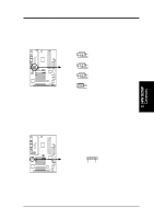
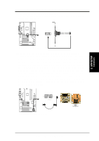
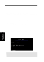
3. HARDWARE SETUP 21) Chassis Intrusion Alarm Connector (4-1 pin ACHA) This connector is for a chassis designed for chassis intrusion detection. Aftermarket toggle switches may also be installed to the chassis panel or on any removable components. Two wires should be available from the chassis to connect to this. When any chassis component is removed, the contact should open and the motherboard will record a chassis intrusion event. If the chassis intrusion alarm connector is not used, a jumper cap must be placed over pins 2 and 3 to prevent unnecessary power loss. +5Volt (Power Supply Stand By) Chassis Signal Ground 01 01 1 P3W ® 1 ACHA P3W Chassis Open Alarm Lead 3. H/W SETUP Connectors 44 ASUS P3W User's Manual
-
 1
1 -
2
-
3
-
4
-
5
-
6
-
7
-
8
-
9
-
10
-
11
-
12
-
13
-
14
-
15
-
16
-
17
-
18
-
19
-
20
-
21
-
22
-
23
-
24
-
25
-
26
-
27
-
28
-
29
-
30
-
31
-
32
-
33
-
34
-
35
-
36
-
37
-
38
-
 39
39 -
 40
40 -
 41
41 -
 42
42 -
 43
43 -
 44
44 -
 45
45 -
 46
46 -
 47
47 -
 48
48 -
 49
49 -
50
-
51
-
52
-
53
-
54
-
55
-
56
-
57
-
58
-
59
-
60
-
61
-
62
-
63
-
64
-
65
-
66
-
67
-
68
-
69
-
70
-
71
-
72
-
73
-
74
-
75
-
76
-
77
-
78
-
79
-
80
-
81
-
82
-
83
-
84
-
85
-
86
-
87
-
88
-
89
-
90
-
91
-
92
-
93
-
94
-
95
-
96
-
97
-
98
-
99
-
100
-
101
-
102
-
103
-
104
-
105
-
106
-
107
-
108
-
109
-
110
-
111
-
112
-
113
-
114
-
115
-
116
-
117
-
118
-
119
-
120
-
121
-
122
-
123
-
124
-
125
-
126
-
127
-
128
 |
 |

44
ASUS P3W User’s Manual
Connectors
3.
H/W SETUP
3.
HARDWARE SETUP
21) Chassis Intrusion Alarm Connector (4-1 pin ACHA)
This connector is for a chassis designed for chassis intrusion detection. After-
market toggle switches may also be installed to the chassis panel or on any
removable components. Two wires should be available from the chassis to con-
nect to this. When any chassis component is removed, the contact should open
and the motherboard will record a chassis intrusion event. If the chassis intru-
sion alarm connector is not used, a jumper cap must be placed over pins 2 and 3
to prevent unnecessary power loss.
P3W Chassis Open Alarm Lead
ACHA
+5Volt
(Power Supply Stand By)
Ground
Chassis Signal
1
1
0
1
0
1
P3W