Asus P5N64 WS Professional User Guide - Page 56
CPU, chassis, and power fan connectors, pin CPU_FAN, 3-pin CHA_FAN1-3, 3-pin PWR_FAN, Chassis
 |
View all Asus P5N64 WS Professional manuals
Add to My Manuals
Save this manual to your list of manuals |
Page 56 highlights
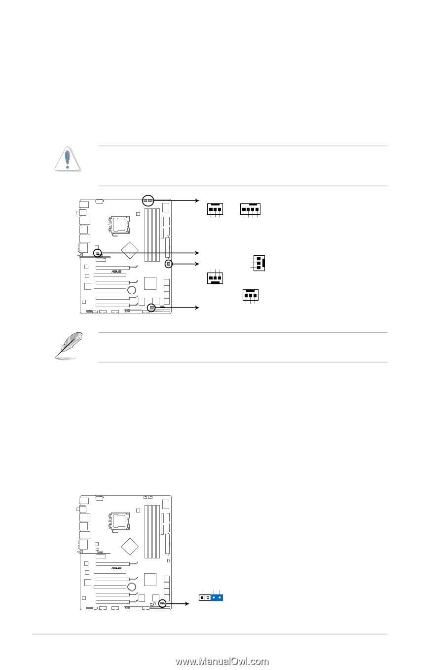
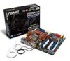
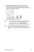
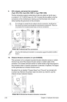
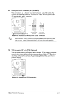
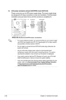
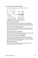
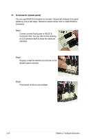
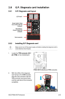
9. CPU, chassis, and power fan connectors (4-pin CPU_FAN, 3-pin CHA_FAN1-3, 3-pin PWR_FAN) The fan connectors support cooling fans of 350 mA~2000 mA (24 W max.) or a total of 1 A~7 A (84 W max.) at +12V. Connect the fan cables to the fan connectors on the motherboard, making sure that the black wire of each cable matches the ground pin of the connector. Do not forget to connect the fan cables to the fan connectors. Insufficient air flow inside the system may damage the motherboard components. These are not jumpers! Do not place jumper caps on the fan connectors! PWR_FAN CPU_FAN PWR_FAN CPU_FAN CPU FAN PWM CPU FAN IN CPU FAN PWR GND Rotation +12V GND P5N64 WS PRO CHA_FAN1 CHA_FAN2 GND +12V Rotation CHA_FAN1 CHA_FAN2 Rotation +12V GND CHA_FAN3 Rotation +12V GND CHA_FAN3 P5N64 WS Professional Fan connectors Only the CPU-FAN and CHA-FAN 1-2 connectors support the ASUS Q-FAN 2 feature. 10. Chassis intrusion connector (4-1 pin CHASSIS) This connector is for a chassis-mounted intrusion detection sensor or switch. Connect one end of the chassis intrusion sensor or switch cable to this connector. The chassis intrusion sensor or switch sends a high-level signal to this connector when a chassis component is removed or replaced. The signal is then generated as a chassis intrusion event. By default, the pin labeled "Chassis Signal" and "Ground" are shorted with a jumper cap. Remove the jumper caps only when you intend to use the chassis intrusion detection feature. +5VSB_MB Chassis Signal GND P5N64 WS PRO CHASSIS P5N64 WS Professional Chassis intrusion connector 2-30 Chapter 2: Hardware information
-
 1
1 -
2
-
3
-
4
-
5
-
6
-
7
-
8
-
9
-
10
-
11
-
12
-
13
-
14
-
15
-
16
-
17
-
18
-
19
-
20
-
21
-
22
-
23
-
24
-
25
-
26
-
27
-
28
-
29
-
30
-
31
-
32
-
33
-
34
-
35
-
36
-
37
-
38
-
39
-
40
-
41
-
42
-
43
-
44
-
45
-
46
-
47
-
48
-
49
-
50
-
 51
51 -
 52
52 -
 53
53 -
 54
54 -
 55
55 -
 56
56 -
 57
57 -
 58
58 -
 59
59 -
 60
60 -
 61
61 -
62
-
63
-
64
-
65
-
66
-
67
-
68
-
69
-
70
-
71
-
72
-
73
-
74
-
75
-
76
-
77
-
78
-
79
-
80
-
81
-
82
-
83
-
84
-
85
-
86
-
87
-
88
-
89
-
90
-
91
-
92
-
93
-
94
-
95
-
96
-
97
-
98
-
99
-
100
-
101
-
102
-
103
-
104
-
105
-
106
-
107
-
108
-
109
-
110
-
111
-
112
-
113
-
114
-
115
-
116
-
117
-
118
-
119
-
120
-
121
-
122
-
123
-
124
-
125
-
126
-
127
-
128
-
129
-
130
-
131
-
132
-
133
-
134
-
135
-
136
-
137
-
138
-
139
-
140
-
141
-
142
-
143
-
144
-
145
-
146
-
147
-
148
-
149
-
150
-
151
-
152
-
153
-
154
-
155
-
156
-
157
-
158
-
159
-
160
-
161
-
162
-
163
-
164
-
165
-
166
-
167
-
168
-
169
-
170
-
171
-
172
-
173
-
174
-
175
-
176
-
177
-
178
-
179
-
180
-
181
-
182
-
183
-
184
-
185
-
186
-
187
-
188
 |
 |