Asus P7P55D LE User Manual - Page 32
Internal connectors
 |
View all Asus P7P55D LE manuals
Add to My Manuals
Save this manual to your list of manuals |
Page 32 highlights
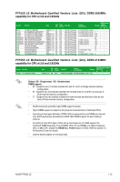
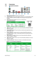
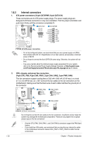
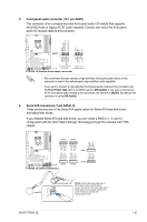
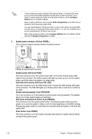
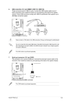
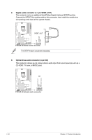
1.8.2 Internal connectors 1. ATX power connectors (24-pin EATXPWR, 8-pin EATX12V) These connectors are for ATX power supply plugs. The power supply plugs are designed to fit these connectors in only one orientation. Find the proper orientation and push down firmly until the connectors completely fit. • For a fully configured system, we recommend that you use a power supply unit (PSU) that complies with ATX 12 V Specification 2.0 (or later version) and provides a minimum power of 600 W. • Do not forget to connect the 8-pin EATX12V power plug. Otherwise, the system will not boot. • If you are uncertain about the minimum power supply requirement for your system, refer to the Recommended Power Supply Wattage Calculator at http://support.asus. com/PowerSupplyCalculator/PSCalculator.aspx?SLanguage=en-us for details. 2. CPU, chassis, and power fan connectors (4-pin CPU_FAN, 4-pin CHA_FAN1, 3-pin CHA_FAN2, 3-pin PWR_FAN) The fan connectors support cooling fans of 350 mA~1000 mA (12 W max.) or a total of 1 A~4 A (48 W max.) at +12V. Connect the fan cables to the fan connectors on the motherboard, making sure that the black wire of each cable matches the ground pin of the connector. Do not forget to connect the fan cables to the fan connectors. Insufficient air flow inside the system may damage the motherboard components. These are not jumpers! Do not place jumper caps on the fan connectors! • Only the CPU_FAN, CHA_FAN 1, and CHA_FAN 2 connectors support the FAN Xpert feature. • If you install two VGA cards, we recommend that you plug the rear chassis fan cable to the motherboard connector labeled CHA_FAN1 or CHA_FAN2 for better thermal environment. 1-20 Chapter 1: Product introduction
-
 1
1 -
2
-
3
-
4
-
5
-
6
-
7
-
8
-
9
-
10
-
11
-
12
-
13
-
14
-
15
-
16
-
17
-
18
-
19
-
20
-
21
-
22
-
23
-
24
-
25
-
26
-
 27
27 -
 28
28 -
 29
29 -
 30
30 -
 31
31 -
 32
32 -
 33
33 -
 34
34 -
 35
35 -
 36
36 -
 37
37 -
38
-
39
-
40
-
41
-
42
-
43
-
44
-
45
-
46
-
47
-
48
-
49
-
50
-
51
-
52
-
53
-
54
-
55
-
56
-
57
-
58
-
59
-
60
-
61
-
62
-
63
-
64
-
65
-
66
-
67
-
68
 |
 |
