Asus P8H61-M LE CSM User Manual - Page 20
Asus P8H61-M LE CSM Manual
 |
View all Asus P8H61-M LE CSM manuals
Add to My Manuals
Save this manual to your list of manuals |
Page 20 highlights
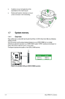
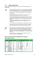
3. Lift the load lever in the direction of the arrow until the load plate is completely lifted. Load plate 4. Remove the PnP cap from the CPU socket by lifting the tab only. PnP cap 5. Position the CPU over the socket, ensuring that the gold triangle is on the bottom‑left corner of the socket, and then fit the socket alignment keys into the CPU notches. The CPU fits in only one correct orientation. DO NOT force the CPU into the socket to prevent bending the connectors on the socket and damaging the CPU! CPU notches Gold triangle mark Alignment keys 1-10 ASUS P8H61-M LE Series
-
 1
1 -
2
-
3
-
4
-
5
-
6
-
7
-
8
-
9
-
10
-
11
-
12
-
13
-
14
-
 15
15 -
 16
16 -
 17
17 -
 18
18 -
 19
19 -
 20
20 -
 21
21 -
 22
22 -
 23
23 -
 24
24 -
 25
25 -
26
-
27
-
28
-
29
-
30
-
31
-
32
-
33
-
34
-
35
-
36
-
37
-
38
-
39
-
40
-
41
-
42
-
43
-
44
-
45
-
46
-
47
-
48
-
49
-
50
-
51
-
52
-
53
-
54
-
55
-
56
-
57
-
58
-
59
-
60
-
61
-
62
-
63
-
64
-
65
-
66
-
67
-
68
 |
 |

ASUS P8H61-M LE Series
1-10
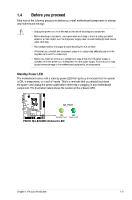
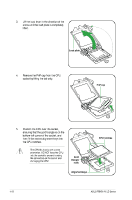
3.
Lift the load lever in the direction of the
arrow until the load plate is completely
lifted.
Load plate
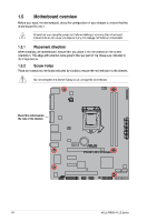
4.
Remove the PnP cap from the CPU
socket by lifting the tab only.
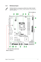
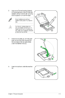
The CPU Fts in only one correct
orientation. DO NOT force the CPU
into the socket to prevent bending
the connectors on the socket and
damaging the CPU!
Gold
triangle
mark
Alignment keys
CPU notches
5.
Position the CPU over the socket,
ensuring that the gold triangle is on the
bottom-left corner of the socket, and
then Ft the socket alignment keys into
the CPU notches.
PnP cap