Asus P8H61-M2 TPM SI User Manual - Page 24
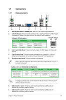
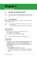
P8H61-M2/TPM/SI System panel connector
 |
View all Asus P8H61-M2 TPM SI manuals
Add to My Manuals
Save this manual to your list of manuals |
Page 24 highlights
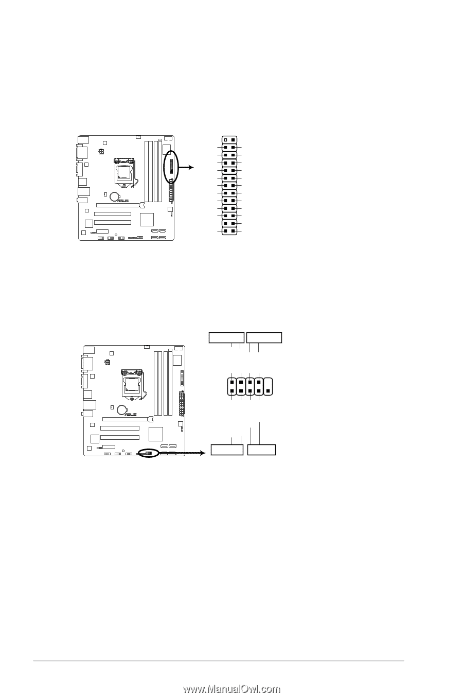
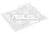
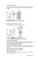
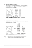
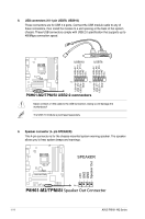
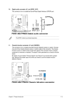
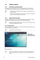
4. LPT connector (26-1 pin LPT) The LPT (Line Printing Terminal) connector supports devices such as a printer. LPT is standardized as IEEE 1284, which is the parallel port interface on IBM PC-compatible computers. LPT P8H61-M2/TPM/SI GND GND GND GND GND GND GND GND SLIN# INIT# ERR# AFD SLCT PE BUSY ACK# PD7 PD6 PD5 PD4 PD3 PD2 PD1 PD0 STB# PIN 1 P8H61-M2/TPM/SI Parallel Port Connector 5. System panel connector (10-1 pin F_PANEL) This connector supports several chassis-mounted functions. F_PANEL PWR LED PWR BTN PLED+ PLEDPWR GND PIN 1 HD_LED+ HD_LED- Ground Reset P8H61-M2/TPM/SI HD_LED RESET P8H61-M2/TPM/SI System panel connector • System power LED (2-pin PLED) This 2-pin connector is for the system power LED. Connect the chassis power LED cable to this connector. The system power LED lights up when you turn on the system power, and blinks when the system is in sleep mode. • Hard disk drive activity LED (2-pin +HDLED) This 2-pin connector is for the HDD Activity LED. Connect the HDD Activity LED cable to this connector. The HD LED lights up or flashes when data is read from or written to the HDD. • ATX power button/soft-off button (2-pin PWRBTN) This 2-pin connector is for the system power button. • Reset button (2-pin RESET) This 2-pin connector is for the chassis-mounted reset button for system reboot without turning off the system power. 1-12 ASUS P8H61-M2 Series
-
 1
1 -
2
-
3
-
4
-
5
-
6
-
7
-
8
-
9
-
10
-
11
-
12
-
13
-
14
-
15
-
16
-
17
-
18
-
 19
19 -
 20
20 -
 21
21 -
 22
22 -
 23
23 -
 24
24 -
 25
25 -
 26
26 -
 27
27 -
 28
28 -
 29
29 -
30
-
31
-
32
-
33
-
34
-
35
-
36
-
37
-
38
-
39
-
40
-
41
-
42
-
43
-
44
-
45
-
46
-
47
-
48
-
49
-
50
-
51
-
52
-
53
-
54
-
55
-
56
-
57
-
58
-
59
 |
 |