Asus PC-DL Deluxe User Guide - Page 58
LINE OUT_L/BLINE_OUT_L are shorted with jumper caps. Remove
 |
View all Asus PC-DL Deluxe manuals
Add to My Manuals
Save this manual to your list of manuals |
Page 58 highlights
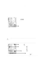
15. Front panel audio connector (10-1 pin FP_AUDIO1) This is an interface for the Intel front panel audio cable that allow convenient connection and control of audio devices. By default, the pins labeled LINE OUT_R/BLINE_OUT_R and the pins LINE OUT_L/BLINE_OUT_L are shorted with jumper caps. Remove the caps only when you are connecting the front panel audio cable. FP_AUDIO1 MIC2 MICPWR Line out_R NC Line out_L AGND +5VA BLINE_OUT_R BLINE_OUT_L PC-DL PC-DL Intel Panel Connector 16. System panel connector (20-pin PANEL1) This connector accommodates several system front panel functions. Power LED Speaker Connector +5VSB LAN_LINK PLED +5V HD_LED+ HD_LEDSpeaker LAN_ACT +5V MLED ExtSMI# Ground PWR Ground Reset Ground PC-DL PC-DL System Panel Connector Message LED SMI Lead Reset SW ATX Power Switch* * Requires an ATX power supply. • System Power LED Lead (3-1 pin PLED) This 3-1 pin connector connects to the system power LED. The LED lights up when you turn on the system power, and blinks when the system is in sleep mode. • Hard Disk Activity Lead (2-pin IDELED) This 2-pin connector is for the HDD LED cable. The read or write activities of the device connected to the any of IDE connectors cause the IDE LED to light up. 2-32 Chapter 2: Hardware information
-
 1
1 -
2
-
3
-
4
-
5
-
6
-
7
-
8
-
9
-
10
-
11
-
12
-
13
-
14
-
15
-
16
-
17
-
18
-
19
-
20
-
21
-
22
-
23
-
24
-
25
-
26
-
27
-
28
-
29
-
30
-
31
-
32
-
33
-
34
-
35
-
36
-
37
-
38
-
39
-
40
-
41
-
42
-
43
-
44
-
45
-
46
-
47
-
48
-
49
-
50
-
51
-
52
-
 53
53 -
 54
54 -
 55
55 -
 56
56 -
 57
57 -
 58
58 -
 59
59 -
 60
60 -
 61
61 -
 62
62 -
 63
63 -
64
-
65
-
66
-
67
-
68
-
69
-
70
-
71
-
72
-
73
-
74
-
75
-
76
-
77
-
78
-
79
-
80
-
81
-
82
-
83
-
84
-
85
-
86
-
87
-
88
-
89
-
90
-
91
-
92
-
93
-
94
-
95
-
96
-
97
-
98
-
99
-
100
-
101
-
102
-
103
-
104
-
105
-
106
-
107
-
108
-
109
-
110
-
111
-
112
-
113
-
114
-
115
-
116
-
117
-
118
-
119
-
120
-
121
-
122
-
123
-
124
 |
 |
