Asus PR-DLSW PR-DLSW M/B manual pdf format file - Page 45
ASUS PR-DLSW motherboard user guide, Chassis alarm lead 4-1 pin CHASSIS, SMBus connector 6-1 pin SMB
 |
View all Asus PR-DLSW manuals
Add to My Manuals
Save this manual to your list of manuals |
Page 45 highlights
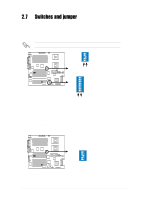
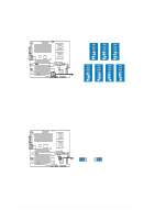
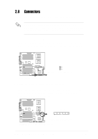
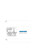
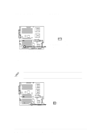
4. Chassis alarm lead (4-1 pin CHASSIS) This lead is for a chassis designed with intrusion detection feature. This requires an external detection mechanism such as a chassis intrusion sensor or microswitch. When you remove any chassis component, the sensor triggers and sends a high-level signal to this lead to record a chassis intrusion event. By default, the pins labeled "Chassis Signal" and "Ground" are shorted with a jumper cap. If you wish to use the chassis intrusion detection feature, remove the jumper cap from the pins. Ground Chassis Signal +5Volt (Power Supply Stand By) ® PR-DLSW CHASSIS PR-DLSW Chassis Open Alarm Lead 5. SMBus connector (6-1 pin SMB) This connector allows you to connect SMBus (System Management Bus) devices. Devices communicate with an SMBus host and/or other SMBus devices using the SMBus interface. SMBus is a specific implementation of an I2C bus, a multi-device bus that allows multiple chips to connect to the same bus and enable each one to act as a master by initiating data transfer. ® PR-DLSW PR-DLSW SMBus Connectors +5V SMBDATA Ground SMBCLK FLOATING SMB 1 ASUS PR-DLSW motherboard user guide 2-19
-
 1
1 -
2
-
3
-
4
-
5
-
6
-
7
-
8
-
9
-
10
-
11
-
12
-
13
-
14
-
15
-
16
-
17
-
18
-
19
-
20
-
21
-
22
-
23
-
24
-
25
-
26
-
27
-
28
-
29
-
30
-
31
-
32
-
33
-
34
-
35
-
36
-
37
-
38
-
39
-
 40
40 -
 41
41 -
 42
42 -
 43
43 -
 44
44 -
 45
45 -
 46
46 -
 47
47 -
 48
48 -
 49
49 -
 50
50 -
51
-
52
-
53
-
54
-
55
-
56
-
57
-
58
-
59
-
60
-
61
-
62
-
63
-
64
-
65
-
66
-
67
-
68
-
69
-
70
-
71
-
72
-
73
-
74
-
75
-
76
-
77
-
78
-
79
-
80
-
81
-
82
-
83
-
84
-
85
-
86
-
87
-
88
-
89
-
90
-
91
-
92
-
93
-
94
-
95
-
96
-
97
-
98
-
99
-
100
-
101
-
102
-
103
-
104
-
105
-
106
-
107
-
108
-
109
-
110
-
111
-
112
-
113
-
114
-
115
-
116
-
117
-
118
-
119
-
120
-
121
-
122
-
123
-
124
-
125
-
126
-
127
-
128
-
129
-
130
 |
 |