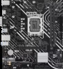
Asus PRIME H610M-D Intel 600 series Channel BIOS UM English - Page 33
Fixed CPU VRM Switching FrequencyKHz, VRM Spread Spectrum, CPU Power Duty Control
 |
View all Asus PRIME H610M-D manuals
Add to My Manuals
Save this manual to your list of manuals |
Page 33 highlights
The following item appears only when CPU VRM Switching Frequency is set to [Manual]. Fixed CPU VRM Switching Frequency(KHz) Allows you to set a higher frequency for a quicker transient response speed. The values range from 250 KHz to 500 KHz with an interval of 50 KHz. The following item appears only when CPU VRM Switching Frequency is set to [Auto]. VRM Spread Spectrum Allows you to reduce the magnitude of peak noise from the VRM. Enable this item to reduce peak noise. Disable this settings when overclocking. Configuration options: [Auto] [Disabled] [Enabled] CPU Power Duty Control CPU power duty control adjusts the duty cycle of each VRM phase based upon current and/or temperature. [T. Probe] Sets the buck controller to balance VRM FET temperatures [Extreme] Select to set the VRM current balance mode. DO NOT remove the thermal module when setting this item to [Extreme]. The thermal conditions should be monitored. CPU Power Phase Control Allows you to set the power phase control of the CPU. [Auto] Automatically selects the power phase control. [Standard] The number of active phases is controlled by the CPU. [Extreme] Sets full phase mode. DO NOT remove the thermal module when setting this item to [Extreme]. The thermal conditions should be monitored. CPU Power Thermal Control Allows you to set the VRM thermal cut-off trip point. 125 Celsius is default and recommended for all overclocking and normal use. Can be set to a lower value if a lower thermal cut-off point is preferred. Use the or to adjust the value. DO NOT remove the VRM heatsink. PRIME / ProArt / TUF GAMING Intel 600 Series BIOS Manual 33
-
 1
1 -
2
-
3
-
4
-
5
-
6
-
7
-
8
-
9
-
10
-
11
-
12
-
13
-
14
-
15
-
16
-
17
-
18
-
19
-
20
-
21
-
22
-
23
-
24
-
25
-
26
-
27
-
 28
28 -
 29
29 -
 30
30 -
 31
31 -
 32
32 -
 33
33 -
 34
34 -
 35
35 -
 36
36 -
 37
37 -
 38
38 -
39
-
40
-
41
-
42
-
43
-
44
-
45
-
46
-
47
-
48
-
49
-
50
-
51
-
52
-
53
-
54
-
55
-
56
-
57
-
58
-
59
-
60
-
61
-
62
-
63
-
64
-
65
-
66
-
67
-
68
-
69
-
70
-
71
-
72
-
73
-
74
-
75
-
76
-
77
-
78
-
79
-
80
-
81
-
82
-
83
-
84
-
85
-
86
-
87
-
88
 |
 |
