Asus PRIME X370-A User Guide - Page 14
PCI Express 2.0 x1 slots, PCI slots, To erase the RTC RAM, Clear RTC RAM 2-pin CLRTC
 |
View all Asus PRIME X370-A manuals
Add to My Manuals
Save this manual to your list of manuals |
Page 14 highlights
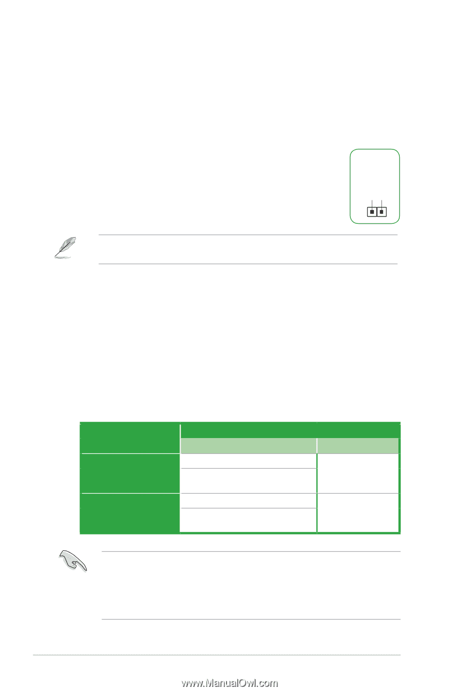
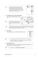
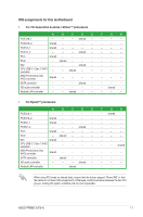
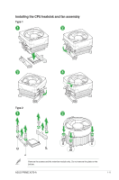
14. Clear RTC RAM (2-pin CLRTC) This header allows you to clear the Real Time Clock (RTC) RAM in CMOS. You can clear the CMOS memory of date, and system setup parameters by erasing the CMOS RTC RAM data. The onboard button cell battery powers the RAM data in CMOS, which include system setup information such as system passwords. To erase the RTC RAM: 1. Turn OFF the computer and unplug the power cord. 2. Use a metal object such as a screwdriver to short the two pins. 3. Plug the power cord and turn ON the computer. 4. Hold down the key during the boot process and enter BIOS setup to re-enter data. +3V_BAT GND CLRTC PIN 1 If the steps above do not help, remove the onboard battery and short the two pins again to clear the CMOS RTC RAM data. After clearing the CMOS, reinstall the battery. 15. PCI Express 2.0 x1 slots This motherboard has two PCI Express 2.0 x1 slots that support PCI Express x1 network cards, SCSI cards, and other cards that comply with the PCI Express specifications. 16. PCI slots The PCI slots support cards such as LAN card, SCSI card, USB card, and other cards that comply with the PCI specifications. 17. PCI Express x16 slots This motherboard supports two PCI Express x16 graphic cards that comply with the PCI Express specifications. VGA configuration Single VGA / PCIe card Dual VGA / PCIe cards PCI Express operating mode PCIe 3.0/ 2.0 x16_1 (gray) x16 (on AMD Ryzen™ processors) x8 (on AMD 7th Generation A-series / Athlon™ processors) x16 (on AMD Ryzen™ processors) x8 (on AMD 7th Generation A-series / Athlon™ processors) PCIe 2.0 x16_2 N/A x4 • In single VGA card mode, use the PCIe 3.0/2.0 x16_1 slot (gray) for a PCI Express x16 graphics card to get better performance. • We recommend that you provide sufficient power when running CrossFireX™ mode. • Connect a chassis fan to the motherboard connector labeled CHA_FAN1/2 when using multiple graphics cards for better thermal environment. 1-6 Chapter 1: Product introduction
-
 1
1 -
2
-
3
-
4
-
5
-
6
-
7
-
8
-
 9
9 -
 10
10 -
 11
11 -
 12
12 -
 13
13 -
 14
14 -
 15
15 -
 16
16 -
 17
17 -
 18
18 -
 19
19 -
20
-
21
-
22
-
23
-
24
-
25
-
26
-
27
-
28
-
29
-
30
-
31
-
32
-
33
-
34
-
35
-
36
-
37
-
38
-
39
-
40
-
41
-
42
-
43
-
44
-
45
-
46
-
47
-
48
-
49
-
50
-
51
-
52
-
53
-
54
-
55
-
56
-
57
-
58
-
59
-
60
 |
 |