Asus ROG CROSSHAIR X670E HERO Users Manual English - Page 32
Alteration Mode switch
 |
View all Asus ROG CROSSHAIR X670E HERO manuals
Add to My Manuals
Save this manual to your list of manuals |
Page 32 highlights
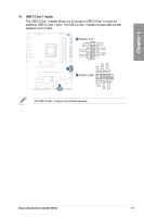
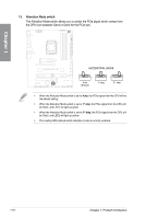
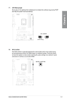
Chapter 1 13. Alteration Mode switch The Alteration Mode switch allows you to switch the PCIe signal which comes from the CPU from between Gen4 or Gen3 for the PCIe slot. • When the Alteration Mode switch is set to Auto, the PCIe signal from the CPU will be the default setting. • When the Alteration Mode switch is set to 1st step, the PCIe signal from the CPU will be Gen4, and LED1 will light up green. • When the Alteration Mode switch is set to 2nd step, the PCIe signal from the CPU will be Gen3, and LED2 will light up yellow. • The nearby LEDs indicate which alteration mode is currently selected. 1-18 Chapter 1: Product Introduction
-
 1
1 -
2
-
3
-
4
-
5
-
6
-
7
-
8
-
9
-
10
-
11
-
12
-
13
-
14
-
15
-
16
-
17
-
18
-
19
-
20
-
21
-
22
-
23
-
24
-
25
-
26
-
 27
27 -
 28
28 -
 29
29 -
 30
30 -
 31
31 -
 32
32 -
 33
33 -
 34
34 -
 35
35 -
 36
36 -
 37
37 -
38
-
39
-
40
-
41
-
42
-
43
-
44
-
45
-
46
-
47
-
48
-
49
-
50
-
51
-
52
-
53
-
54
-
55
-
56
-
57
-
58
-
59
-
60
-
61
-
62
-
63
-
64
-
65
-
66
-
67
-
68
-
69
-
70
-
71
-
72
-
73
-
74
-
75
-
76
-
77
-
78
-
79
-
80
-
81
-
82
-
83
-
84
-
85
-
86
-
87
-
88
-
89
-
90
-
91
-
92
-
93
-
94
-
95
-
96
 |
 |

1-18
Chapter 1: Product Introduction
Chapter 1
13.
Alteration Mode switch
The Alteration Mode switch allows you to switch the PCIe signal which comes from
the CPU from between Gen4 or Gen3 for the PCIe slot.
•
When the Alteration Mode switch is set to
Auto
, the PCIe signal from the CPU will be
the default setting.
•
When the Alteration Mode switch is set to
1
st
step
, the PCIe signal from the CPU will
be Gen4, and LED1 will light up green.
•
When the Alteration Mode switch is set to
2
nd
step
, the PCIe signal from the CPU will
be Gen3, and LED2 will light up yellow.
•
The nearby LEDs indicate which alteration mode is currently selected.