Asus ROG STRIX B660-G GAMING WIFI Users Manual English - Page 31
Storage Device Activity LED header HDD_LED, Power Button/Soft-off Button header PWRSW
 |
View all Asus ROG STRIX B660-G GAMING WIFI manuals
Add to My Manuals
Save this manual to your list of manuals |
Page 31 highlights
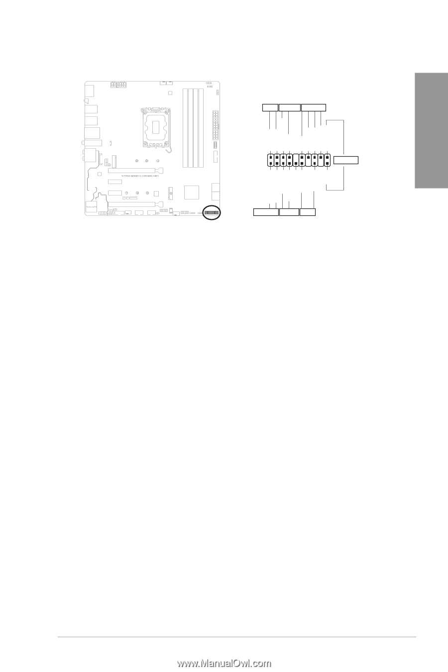
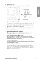
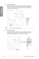
Chapter 1 19. System Panel header The System Panel header supports several chassis-mounted functions. PLED PWRSW SPEAKER PLED+ PLEDPWRBTN# GND +5V Ground Ground Speaker Intruder# PANEL PIN 1 CHASSIS HDD_LED+ HDD_LED- Ground RSTCON# NC PLED+ PLED- GND HDD_LED RESET PLED • System Power LED header (PLED) The 2-pin and/or 3-1 pin headers allow you to connect the System Power LED. The System Power LED lights up when the system is connected to a power source, or when you turn on the system power, and blinks when the system is in sleep mode. • Storage Device Activity LED header (HDD_LED) The 2-pin header allows you to connect the Storage Device Activity LED. The Storage Device Activity LED lights up or blinks when data is read from or written to the storage device or storage device add-on card. • System Warning Speaker header (SPEAKER) The 4-pin header allows you to connect the chassis-mounted system warning speaker. The speaker allows you to hear system beeps and warnings. • Power Button/Soft-off Button header (PWRSW) The 3-1 pin header allows you to connect the system power button. Press the power button to power up the system, or put the system into sleep or soft-off mode (depending on the operating system settings). • Reset button header (RESET) The 2-pin header allows you to connect the chassis-mounted reset button. Press the reset button to reboot the system. • Chassis intrusion header (CHASSIS) The 2-pin header allows you to connect the chassis-mounted intrusion detection sensor or switch. The chassis intrusion sensor or switch sends a high-level signal to the header when a chassis component is removed or replaced, the signal is then generated as a chassis intrusion event. ROG STRIX B660-G GAMING WIFI 1-19
-
 1
1 -
2
-
3
-
4
-
5
-
6
-
7
-
8
-
9
-
10
-
11
-
12
-
13
-
14
-
15
-
16
-
17
-
18
-
19
-
20
-
21
-
22
-
23
-
24
-
25
-
 26
26 -
 27
27 -
 28
28 -
 29
29 -
 30
30 -
 31
31 -
 32
32 -
 33
33 -
 34
34 -
 35
35 -
 36
36 -
37
-
38
-
39
-
40
-
41
-
42
-
43
-
44
-
45
-
46
-
47
-
48
-
49
-
50
-
51
-
52
-
53
-
54
-
55
-
56
-
57
-
58
-
59
-
60
-
61
-
62
-
63
-
64
-
65
-
66
-
67
-
68
-
69
-
70
-
71
-
72
-
73
-
74
 |
 |