Asus ROG STRIX H270I GAMING STRIX H270I GAMING Users ManualEnglish - Page 14
Motherboard layout, 1.8 Internal connectors, 2.1 Rear I/O connection
 |
View all Asus ROG STRIX H270I GAMING manuals
Add to My Manuals
Save this manual to your list of manuals |
Page 14 highlights
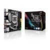
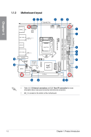
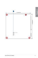
Chapter 1 1.1.2 Motherboard layout 1 23 4 17.0cm(6.7in) 56 HDMI DP EATX12V DIGI +VRM LAN2_USB3_78 Realtek® (Bottom) RTL8111H BOOT_DEVICE_LED VGA_LED DRAM_LED CPU_LED CPU_FAN AIO_PUMP RGBLED 7 1 17.0cm(6.7in) EATXPWR DDR4 DIMM_B1 (64bit, 288-pin module) DDR4 DIMM_A1 (64bit, 288-pin module) USB3_56 LGA1151 16 15 LAN1_USB3_34 Intel® (Bottom) I219V M.2(WIFI) BATT_CON Super I/O AUDIO AAFP 2280 SupremeFX S1220A Codec 2260 TPM PCIE SATA IRST X4 VV 128Mb BIOS Intel® H270 CHA_FAN PCIEX16 14 4 M.2_1(SOCKET3) M.2_2(SOCKET3)Bottom SATA6G_4 SATA6G_3 CLRTC 13 11 USB3_12 SATA6G_2 SATA6G_1 SPEAKER F_PANEL RGB_HEADER 8 9 10 11 12 • Refer to 1.1.8 Internal connectors and 2.2.1 Rear I/O connection for more information about rear panel connectors and internal connectors. • M2_2 is located on the bottom of the motherboard. 1-2 Chapter 1: Product Introduction
-
 1
1 -
2
-
3
-
4
-
5
-
6
-
7
-
8
-
 9
9 -
 10
10 -
 11
11 -
 12
12 -
 13
13 -
 14
14 -
 15
15 -
 16
16 -
 17
17 -
 18
18 -
 19
19 -
20
-
21
-
22
-
23
-
24
-
25
-
26
-
27
-
28
-
29
-
30
-
31
-
32
-
33
-
34
-
35
-
36
-
37
-
38
-
39
-
40
-
41
-
42
-
43
-
44
-
45
-
46
-
47
-
48
-
49
-
50
-
51
-
52
-
53
-
54
-
55
-
56
-
57
-
58
-
59
-
60
-
61
-
62
-
63
-
64
-
65
-
66
-
67
-
68
-
69
-
70
-
71
-
72
-
73
-
74
-
75
 |
 |
