Asus ROG STRIX H270I GAMING STRIX H270I GAMING Users ManualEnglish - Page 16
Central Processing Unit (CPU), STRIX H270I GAMING CPU socket LGA1151
 |
View all Asus ROG STRIX H270I GAMING manuals
Add to My Manuals
Save this manual to your list of manuals |
Page 16 highlights
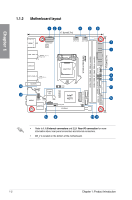
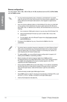
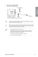
Chapter 1 Layout contents Connectors/Jumpers/Buttons and switches/Slots 1. ATX power connectors (24-pin EATXPWR, 8-pin EATX12V) 2. M.2 sockets (M.2_1~2) 3. LGA1151 CPU socket 4. CPU, AIO pump, and chassis fan connectors (4-pin CPU_FAN, 4-pin AIO_PUMP, 4-pin CHA_FAN) 5. DDR4 DIMM slots 6. POST State LEDs 7. RGB LED Standby power LED (SB_PWR) 8. RGB header (4-pin RGB_HEADER) 9. System panel connector (10-1 pin PANEL) 10. Speaker connector (4-pin SPEAKER) 11. Intel® Serial ATA 6 Gb/s connectors (7-pin SATA6G_1~4) 12. USB 3.0 connectors (20-1 pin USB3_12) 13. Clear RTC RAM jumper (2-pin CLRTC) 14. TPM connector (14-1 pin TPM) 15. Front panel audio connector (10-1 pin AAFP) 16. RTC Battery header (2-pin BATT_CON) Page 1-12 1-15 1-4 1-14 1-5 1-10 1-10 1-9 1-16 1-11 1-13 1-11 1-8 1-13 1-12 1-8 1.1.3 Central Processing Unit (CPU) The motherboard comes with a surface mount LGA1151 socket designed for the 7th / 6th Generation Intel® Core™ i7 / Intel® Core™ i5 / Intel® Core™ i3, Pentium®, and Celeron® processors. STRIX H270I GAMING CPU socket LGA1151 1-4 Chapter 1: Product Introduction
-
 1
1 -
2
-
3
-
4
-
5
-
6
-
7
-
8
-
9
-
10
-
 11
11 -
 12
12 -
 13
13 -
 14
14 -
 15
15 -
 16
16 -
 17
17 -
 18
18 -
 19
19 -
 20
20 -
 21
21 -
22
-
23
-
24
-
25
-
26
-
27
-
28
-
29
-
30
-
31
-
32
-
33
-
34
-
35
-
36
-
37
-
38
-
39
-
40
-
41
-
42
-
43
-
44
-
45
-
46
-
47
-
48
-
49
-
50
-
51
-
52
-
53
-
54
-
55
-
56
-
57
-
58
-
59
-
60
-
61
-
62
-
63
-
64
-
65
-
66
-
67
-
68
-
69
-
70
-
71
-
72
-
73
-
74
-
75
 |
 |
