Asus SP98AGP-X SP98AGP-X User Manual - Page 14
Installation Steps, Jumpers
 |
View all Asus SP98AGP-X manuals
Add to My Manuals
Save this manual to your list of manuals |
Page 14 highlights
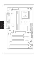
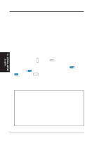
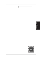
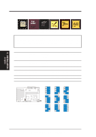
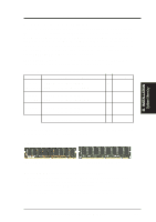
III. INSTALLATION Jumpers III. INSTALLATION Installation Steps Before using your computer, you must complete the following steps: 1. Set Jumpers on the Motherboard 2. Install System Memory 3. Install the Central Processing Unit (CPU) 4. Install Expansion Cards 5. Connect Ribbon Cables, Cabinet Wires, and Power Supply 6. Setup the BIOS Software 1. Jumpers Several hardware settings are made through the use of jumper caps to connect jumper pins (JP) on the motherboard. See "Motherboard Layout" for locations of jumpers. The jumper settings will be described numerically such as [----], [1-2], [2-3] for no connection, connect pins 1&2, and connect pins 2&3 respectively. Pin 1 for our moth- PIN 1 PIN 1 erboards is always on top or on the left when holding the motherboard with the keyboard connector away from yourself. A "1" is written besides pin 1 on jumpers with three pins. The jumpers will also be shown graphically such as to connect pins 1&2 and to connect pins 2&3. Jumpers with two pins will be shown as for Short (On) and for Open (Off). For manufacturing simplicity, the jump- ers may be sharing pins from other groups. Use the diagrams in this manual instead of following the pin layout on the board. Settings with two jumper numbers require that both jumpers be moved together. To connect the pins, simply place a plastic jumper cap over the two pins as diagramed. WARNING! Computer motherboards, baseboards and components, such as SCSI cards, contain very delicate Integrated Circuit (IC) chips. To protect them against damage from static electricity, you should follow some precautions whenever you work on your computer. 1. Unplug your computer when working on the inside. 2. Use a grounded wrist strap before handling computer components. If you do not have one, touch both of your hands to a safely grounded object or to a metal object, such as the power supply case. 3. Hold components by the edges and try not to touch the IC chips, leads or connectors, or other components. 4. Place components on a grounded antistatic pad or on the bag that came with the component whenever the components are separated from the system. 14 ASUS SP98AGP-X User's Manual
-
 1
1 -
2
-
3
-
4
-
5
-
6
-
7
-
8
-
 9
9 -
 10
10 -
 11
11 -
 12
12 -
 13
13 -
 14
14 -
 15
15 -
 16
16 -
 17
17 -
 18
18 -
 19
19 -
20
-
21
-
22
-
23
-
24
-
25
-
26
-
27
-
28
-
29
-
30
-
31
-
32
-
33
-
34
-
35
-
36
-
37
-
38
-
39
-
40
-
41
-
42
-
43
-
44
-
45
-
46
-
47
-
48
-
49
-
50
-
51
-
52
-
53
-
54
-
55
-
56
-
57
-
58
-
59
-
60
-
61
-
62
-
63
-
64
 |
 |