Asus T3-P5G43 User Manual - Page 18
Internal components
 |
View all Asus T3-P5G43 manuals
Add to My Manuals
Save this manual to your list of manuals |
Page 18 highlights
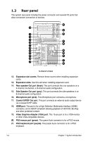
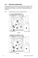
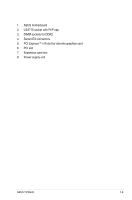
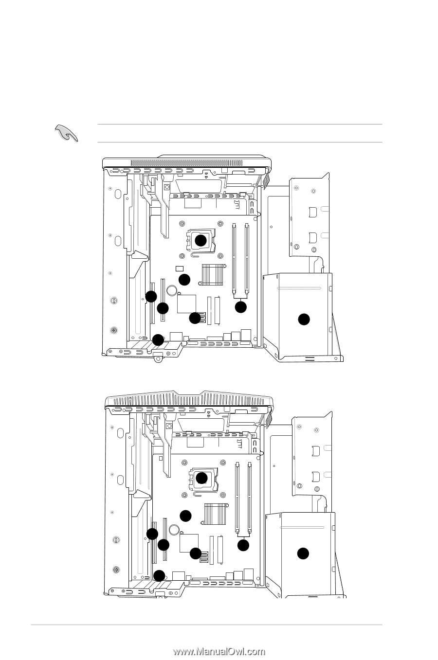
1.4 Internal components The illustration below is the internal view of the system when you remove the top cover and the power supply unit. The installed components are labeled for your reference. Proceed to Chapter 2 for instructions on installing additional system components. The illustration shows an open chassis lifted at a 90o angle. 2 1 6 5 3 4 8 7 T3-P5G43 2 1 6 5 3 4 8 7 T4-P5G43 1-8 Chapter 1: System introduction
-
 1
1 -
2
-
3
-
4
-
5
-
6
-
7
-
8
-
9
-
10
-
11
-
12
-
 13
13 -
 14
14 -
 15
15 -
 16
16 -
 17
17 -
 18
18 -
 19
19 -
 20
20 -
 21
21 -
 22
22 -
 23
23 -
24
-
25
-
26
-
27
-
28
-
29
-
30
-
31
-
32
-
33
-
34
-
35
-
36
-
37
-
38
-
39
-
40
-
41
-
42
-
43
-
44
-
45
-
46
-
47
-
48
-
49
-
50
-
51
-
52
-
53
-
54
-
55
-
56
-
57
-
58
-
59
-
60
-
61
-
62
-
63
-
64
-
65
-
66
-
67
-
68
-
69
-
70
-
71
-
72
-
73
-
74
-
75
-
76
-
77
-
78
-
79
-
80
-
81
-
82
-
83
-
84
-
85
-
86
-
87
-
88
-
89
-
90
-
91
-
92
-
93
-
94
-
95
-
96
-
97
-
98
-
99
-
100
-
101
-
102
-
103
-
104
 |
 |
1-8
Chapter 1: System introduction
1.4
Internal components
The illustration below is the internal view of the system when you remove the top
cover and the power supply unit. The installed components are labeled for your
reference. Proceed to Chapter 2 for instructions on installing additional system
components.
The illustration shows an open chassis lifted at a 90
o
angle.
1
2
4
5
6
7
8
2
1
3
8
5
6
4
7
T3-P5G43
T4-P5G43
3