Asus T3-P5G43 User Manual - Page 35
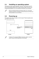
Installing an optical drive
 |
View all Asus T3-P5G43 manuals
Add to My Manuals
Save this manual to your list of manuals |
Page 35 highlights
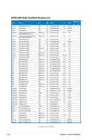
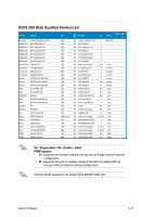
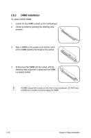
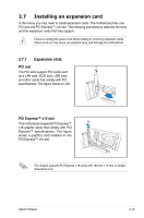
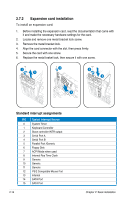
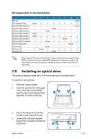
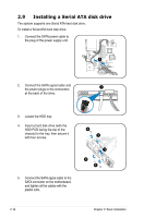
IRQ assignments for this motherboard A B C D E F G H PCI slot -- -- -- -- -- -- -- shared PCI Express x16 slot shared -- -- -- -- -- -- -- Onboard USB controller 0 -- -- -- -- -- -- -- shared Onboard USB controller 1 -- -- -- shared -- -- -- -- Onboard USB controller 2 -- -- shared -- -- -- -- -- Onboard USB controller 3 shared -- -- -- -- -- -- -- Onboard USB controller 4 shared -- -- -- -- -- -- -- Onboard USB controller 5 -- -- -- -- -- Shared -- -- Onboard USB 2.0 controller -- -- Shared -- -- -- -- -- Onboard Azalia Audio -- -- -- -- -- -- Shared -- Onboard IDE -- -- Shared -- -- -- -- -- Onboard LAN -- Shared -- -- -- -- -- -- Onboard 1394 -- -- -- shared -- -- -- -- When using a PCI card on shared slots, ensure that the drivers support "Share IRQ" or that the cards do not need IRQ assignments. Otherwise, conflicts will arise between the two PCI groups, making the system unstable and the card inoperable. 2.8 Installing an optical drive The barebone system comes with a 5.25-inch drive bays for an optical drive. To install an optical drive: 1. Place the chassis upright. 2. Insert the optical drive to the upper 5.25 in drive bay, then carefully push the drive until its screw holes 2 2 align with the holes on the bay. 3. Secure the optical drive with four screws on both sides of the bay. 4. Connect the IDE and the power plugs to the connectors at the back of the drive. 3 ASUS T-P5G43 3 2-15
-
 1
1 -
2
-
3
-
4
-
5
-
6
-
7
-
8
-
9
-
10
-
11
-
12
-
13
-
14
-
15
-
16
-
17
-
18
-
19
-
20
-
21
-
22
-
23
-
24
-
25
-
26
-
27
-
28
-
29
-
 30
30 -
 31
31 -
 32
32 -
 33
33 -
 34
34 -
 35
35 -
 36
36 -
 37
37 -
 38
38 -
 39
39 -
 40
40 -
41
-
42
-
43
-
44
-
45
-
46
-
47
-
48
-
49
-
50
-
51
-
52
-
53
-
54
-
55
-
56
-
57
-
58
-
59
-
60
-
61
-
62
-
63
-
64
-
65
-
66
-
67
-
68
-
69
-
70
-
71
-
72
-
73
-
74
-
75
-
76
-
77
-
78
-
79
-
80
-
81
-
82
-
83
-
84
-
85
-
86
-
87
-
88
-
89
-
90
-
91
-
92
-
93
-
94
-
95
-
96
-
97
-
98
-
99
-
100
-
101
-
102
-
103
-
104
 |
 |