Asus TS300-E3 PA4 TS300-E3
Asus TS300-E3 PA4 Manual
 |
View all Asus TS300-E3 PA4 manuals
Add to My Manuals
Save this manual to your list of manuals |
Asus TS300-E3 PA4 manual content summary:
- Asus TS300-E3 PA4 | TS300-E3 - Page 1
TS300-E3/PA4 & PS4 Intel® Pentium® 4/Pentium® D LGA775 Pedestal/5U Rackmount Server 1066/800 MHz Front Side Bus - Asus TS300-E3 PA4 | TS300-E3 - Page 2
, and should not be construed as a commitment by ASUS. ASUS assumes no responsibility or liability for any errors or inaccuracies that may appear in this manual, including the products and software described in it. Product warranty or service will not be extended if: (1) the product is repaired - Asus TS300-E3 PA4 | TS300-E3 - Page 3
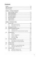
Contents Notices...vii Safety information viii About this guide ix Chapter 1: Product introduction 1.1 System package contents 1-2 1.2 System specifications 1-3 1.2 System specifications 1-4 1.3 Front panel features 1-5 1.4 Rear panel features 1-6 1.5 Internal features 1-7 1.6 LED information - Asus TS300-E3 PA4 | TS300-E3 - Page 4
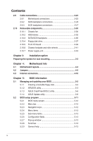
BIOS information 5.1 Managing and updating your BIOS 5-2 5.1.1 Creating a bootable floppy disk 5-2 5.1.2 AFUDOS utility 5-3 5.1.3 ASUS CrashFree BIOS 2 utility 5-6 5.1.4 ASUS Update utility 5-8 5.2 BIOS setup program 5-11 5.2.1 BIOS menu screen 5-12 5.2.2 Menu bar 5-12 5.2.3 Navigation keys - Asus TS300-E3 PA4 | TS300-E3 - Page 5
22 5.4.4 Onboard Devices Configuration 5-26 5.4.5 PCI PnP 5-27 5.5 Power Configuration 5-28 5.5.1 ACPI APIC support 5-28 5.5.2 APM configuration 5-28 5.5.3 Hardware Monitor 5-31 5.6 Server menu 5-33 Remote Access Configuration 5-33 5.7 Boot menu 5-35 5.7.1 Boot Device Priority 5-35 5.7.2 Boot - Asus TS300-E3 PA4 | TS300-E3 - Page 6
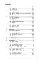
ver. 3.0 7-13 7.3 VGA driver installation 7-14 7.3.1 Windows® 2000 Server 7-14 7.3.2 Windows® 2003 Server 7-15 7.3.3 Red Hat® Enterprise ver. 3.0 7-15 7.4 Management applications and utilities installation 7-16 7.4.1 Running the support CD 7-16 7.4.2 Drivers menu 7-16 7.4.3 Management - Asus TS300-E3 PA4 | TS300-E3 - Page 7
. This equipment generates, uses and can radiate radio frequency energy and, if not installed and used in accordance with manufacturerʼs instructions, may cause harmful interference to radio communications. However, there is no guarantee that interference will not occur in a particular installation - Asus TS300-E3 PA4 | TS300-E3 - Page 8
a qualified service technician or your dealer. Operation Safety • Any mechanical operation on this server must be conducted by certified or experienced engineers. • Before operating the server, carefully read all the manuals included with the server package. • Before using the server, make sure all - Asus TS300-E3 PA4 | TS300-E3 - Page 9
to install the drivers for system components. This chapter also describes the software applications that the barebone server supports. 8. Appendix: Reference information This section provides information about the power supply unit and a troubleshooting guide for solving common problems when using - Asus TS300-E3 PA4 | TS300-E3 - Page 10
note of the following symbols used throughout this manual. WARNING: Information to prevent injury to yourself when trying to complete a task. CAUTION: Information to prevent damage to the components when trying to complete a task. IMPORTANT: Instructions that you MUST follow to complete a task. NOTE - Asus TS300-E3 PA4 | TS300-E3 - Page 11
Product introduction Chapter 1 This chapter describes the general features of the barebone server, including sections on the front panel and rear panel specifications. ASUS TS300-E3/PA4 & PS4 1- - Asus TS300-E3 PA4 | TS300-E3 - Page 12
CDs • TS300-E3 support CD with ASWM* • Computer Associates® eTrust™ anti-virus CD Documentation • ASUS TS300-E3 user guide • ASUS ASWM 2.0 user guide Optional items • 52x IDE CD-ROM or 16X DVD-ROM drive • ASUS TS300-E3 rackmount rail kit *ASUS System Web-based Management Configuration PA4 PS4 - Asus TS300-E3 PA4 | TS300-E3 - Page 13
specifications The ASUS TS300-E3 is a barebone server system featuring the ASUS P5MT Series motherboard. The server supports an Intel® supports: - 1 x Ultra 320 SCSI channel with RAID 0, RAID 1, and RAID 10 configuration - Zero-Channel RAID (optional) (continued on the next page) ASUS TS300-E3/PA4 - Asus TS300-E3 PA4 | TS300-E3 - Page 14
1 x PCI-X 100 MHz/64-bit slot (PCI-X 1.0) 1 x PCI-X 100 MHz/64-bit slot (supports ZCR, PCI-X 1.0)* (colored green on PS4 model) 1 x PCI Express™ x16 slot (x8 Link)** 1 x Mini-PCI socket for the ASUS Server Management Board 1 x 3.25-inch FDD bay 3 x 5.25-inch drive bays 2 x USB 2.0 ports 1 x Serial - Asus TS300-E3 PA4 | TS300-E3 - Page 15
1.3 Front panel features The TS300-E3 chassis displays a stylish front bezel with lock. The bezel covers the system components on the front panel and button Reset button Message LED HDD access LED Power LED Floppy disk drive USB 2.0 ports Security lock Drive bays ASUS TS300-E3/PA4 & PS4 1-5 - Asus TS300-E3 PA4 | TS300-E3 - Page 16
1.4 Rear panel features The rear panel includes a slot for the motherboard rear I/O ports, expansion slots, a chassis lock and intrusion switch, a vent for the system fan, and power supply module. Power supply module Power connector PS/2 mouse port PS/2 keyboard port USB 2.0 ports Serial port - Asus TS300-E3 PA4 | TS300-E3 - Page 17
4 • • 5 • • • • 3 10 8 9 1. Power supply unit 2. Chassis fan 3. ASUS P5MT motherboard 4. Chassis intrusion switch 5. Expansion card locks 6. Optical drive 7. 2 x 5.25-inch drive bays 8. HDD blower (HDD drive cage inside) 9. Front I/0 board 10. SATA backplane ASUS TS300-E3/PA4 & PS4 1-7 - Asus TS300-E3 PA4 | TS300-E3 - Page 18
PS4 (4 hot-swap SCSI configuration) 6 1 • 7 • 2 4 • • 5 • • • • 3 10 8 9 1. Power supply unit 2. Chassis fan 3. ASUS P5MT-S motherboard 4. Chassis intrusion switch 5. Expansion card locks 6. Optical drive 7. 2 x 5.25-inch drive bays 8. HDD blower (HDD drive cage inside) 9. Front I/0 - Asus TS300-E3 PA4 | TS300-E3 - Page 19
Access Fault-Tolerant Enclosure (on PS4 model only) The Power, HDD Access, and Message LEDs are visible even if the system front bezel is closed. ASUS TS300-E3/PA4 & PS4 1-9 - Asus TS300-E3 PA4 | TS300-E3 - Page 20
1-10 Chapter 1: Product introduction - Asus TS300-E3 PA4 | TS300-E3 - Page 21
Chapter 2 This chapter lists the hardware setup procedures that you have to perform when installing or removing system components. Hardware setup ASUS TS300-E3/PA4 & PS4 2- - Asus TS300-E3 PA4 | TS300-E3 - Page 22
and set it aside. 1 2 Viewing the internal structure Without the side cover, the internal structure and installed components of the barebone server vary depending on the model you purchased. Refer to section "1.5 Internal features" for the different model configurations. Perform the procedures in - Asus TS300-E3 PA4 | TS300-E3 - Page 23
to access the DIMM sockets and internal connectors. Refer to section "2.10 Removable components" for instructions. 2.1.2 Reinstalling the side cover To reinstall the side cover: 1. Match and insert the the two screws you removed earlier to secure the side cover. 3 3 ASUS TS300-E3/PA4 & PS4 2-3 - Asus TS300-E3 PA4 | TS300-E3 - Page 24
2.2 Motherboard overview The barebone server comes with the P5MT (PA4 model) or P5MT-S (PS4 model) motherboard already installed. The motherboard is secured to the chassis by nine (9) screws as indicated by the circles in the - Asus TS300-E3 PA4 | TS300-E3 - Page 25
of the socket box should face you. To prevent damage to the socket pins, do not remove the PnP cap unless you are installing a CPU. ASUS TS300-E3/PA4 & PS4 2-5 - Asus TS300-E3 PA4 | TS300-E3 - Page 26
3. Lift the load lever in the direction of the arrow to a 135º angle. 4. Lift the load plate with your thumb and forefinger to a 100º angle (A), then push the PnP cap from the load plate window to remove (B). B A Load plate 5. Position the CPU over the socket, making sure that the gold triangle - Asus TS300-E3 PA4 | TS300-E3 - Page 27
tab. B The motherboard supports Intel® Pentium® 4 LGA775 processors with the Intel® Enhanced Memory 64 Technology (EM64T), Enhanced Intel SpeedStep® Technology (EIST), and Hyper-Threading Technology. Refer to the Appendix for more information on these CPU features. ASUS TS300-E3/PA4 & PS4 2-7 - Asus TS300-E3 PA4 | TS300-E3 - Page 28
2.3.2 Installing the CPU heatsink and airduct assembly The TS300-E3 comes with a proprietary CPU heatsink and airduct, which come in separate boxes when you receive the package. You have to assemble the CPU heatsink and - Asus TS300-E3 PA4 | TS300-E3 - Page 29
Series CPU fan connector Do not forget to connect the CPU fan connector! Hardware monitoring errors can occur if you fail to plug the connector. ASUS TS300-E3/PA4 & PS4 2-9 - Asus TS300-E3 PA4 | TS300-E3 - Page 30
Data Rate II (DDR2) Dual Inline Memory Modules (DIMM) sockets to support 240-pin DDR modules. The figure illustrates the location of the DDR DIMM modules from the same vendor. Refer to the DDR2 Qualified Vendors List at the ASUS web site. • When installing one or two DIMMs, install the DIMM(s) to the - Asus TS300-E3 PA4 | TS300-E3 - Page 31
. • The DDR2 DIMM sockets do not support DDR DIMMs. DO not install DDR DIMMs Support the DIMM lightly with your fingers when pressing the retaining clips. The DIMM might get damaged when it flips out 1 with extra force. 2. Remove the DIMM from the socket. 2 1 DDR2 DIMM notch ASUS TS300-E3/PA4 - Asus TS300-E3 PA4 | TS300-E3 - Page 32
2.5 Front panel assembly 2.5.1 Removing the front panel assembly Before you can install a 5.25-inch drive, you should first remove the front panel assembly (front bezel and front panel cover). The front panel assembly is attached to the chassis through three hooked tabs on the left side and four - Asus TS300-E3 PA4 | TS300-E3 - Page 33
4. Unhook the hinge-like tabs from the holes on the right side of the front panel to completely detach the front panel assembly from the chassis. Do not use too much force when removing the front panel assembly. Hinge-like tab ASUS TS300-E3/PA4 & PS4 2-13 - Asus TS300-E3 PA4 | TS300-E3 - Page 34
2.5.2 Reinstalling the front panel assembly To reinstall the front panel assembly (front bezel and front panel cover): 1. Insert the four hinge-like tabs to the holes on the right edge of the chassis. 2. Swing the front panel to the left and fit the four (4) hooked tabs to the left side of the - Asus TS300-E3 PA4 | TS300-E3 - Page 35
that secure the metal cover of the bay where you want to install the drive. 2. Insert the optical drive into the 5.25-inch drive bay. ASUS TS300-E3/PA4 & PS4 2-15 - Asus TS300-E3 PA4 | TS300-E3 - Page 36
3. Make sure that the drive and bay hole align as shown. When in place, the drive protrudes about an inch from the front panel. 4. Secure the drive with a screw. 5. Connect the IDE cable to the IDE connector on the back of the drive. 6. Connect a 4-pin plug from the power supply to the power - Asus TS300-E3 PA4 | TS300-E3 - Page 37
hooked tabs on each side of the bay cover. 8. Reinstall the front panel assembly when done. Refer to section "2.5.2 Reinstalling the front panel assembly" for instructions. ASUS TS300-E3/PA4 & PS4 2-17 - Asus TS300-E3 PA4 | TS300-E3 - Page 38
Installing a hot-swap SATA/SCSI HDD Follow the instructions in this section to install a hot-swap SATA (PA4 model) or SCSI (PS4 model) hard disk out of the bay. 4. An empty drive tray requires a metal bracket for support. Use a Phillips (cross) screwdriver to remove the bracket when you are ready - Asus TS300-E3 PA4 | TS300-E3 - Page 39
until it clicks, and secures the drive tray in place. The drive tray is correctly placed when its front edge aligns with the bay edge. ASUS TS300-E3/PA4 & PS4 2-19 - Asus TS300-E3 PA4 | TS300-E3 - Page 40
2.7.2 Installing an HDD dummy cover The HDD dummy covers come pre-installed on the front panel bezel. In case you removed the covers, follow these steps to re-install them. To install an HDD dummy cover: 1. From the inside of the front panel assembly, insert the flat end of a dummy cover into the - Asus TS300-E3 PA4 | TS300-E3 - Page 41
. 4. Press the card firmly until it is properly seated on the slot. 5. Secure the card to the chassis with the bracket screw you removed earlier. ASUS TS300-E3/PA4 & PS4 2-21 - Asus TS300-E3 PA4 | TS300-E3 - Page 42
2.8.2 Removing an expansion card To remove an expansion card: 1. Remove the screw that secures the card to the chassis. 2. Carefully remove the card from the slot. 3. Reinstall the metal bracket and secure it to the chassis with the screw that you removed earlier. 2-22 Chapter 2: Hardware setup - Asus TS300-E3 PA4 | TS300-E3 - Page 43
fan 1/2 10. Front panel cable 5. Front fan 1/2 11. Floppy disk drive 6. Serial ATA connectors 12. Primary IDE cable 13. SCSI connector (for PS4 Model only) ASUS TS300-E3/PA4 & PS4 2-23 - Asus TS300-E3 PA4 | TS300-E3 - Page 44
model only) A SATA backplane comes pre-installed in the TS300-E3 PA4 model. The SATA backplane has four 15-pin SATA connectors to support Serial ATA hard disk drives. The backplane design incorporates a hot swap feature to allow easy connection or removal of SATA hard disks. The LED on - Asus TS300-E3 PA4 | TS300-E3 - Page 45
CR2032 3V Lithium Cell CMOS Power BUZZ1 USBPW34 USB34 PANEL1 Intel 6702 PXH FLOPPY1 PRI_IDE1 30.5cm (12in) SATA RAID controller SATA4 SATA2 SATA1 SATA3 ASUS TS300-E3/PA4 & PS4 2-25 - Asus TS300-E3 PA4 | TS300-E3 - Page 46
SATA backplane jumper settings and HDD ID assignments The 6-pin jumper J3 allows you to define your desired SATA configuration. The picture below shows the location of jumper J3 with pins 1-3 and 2-4 shorted. Refer to the table for the jumper settings and the appropriate ID# for each SATA HDD bay. - Asus TS300-E3 PA4 | TS300-E3 - Page 47
model only) A SCSI backplane comes pre-installed in the TS300-E3 PS4 model. The SCSI backplane has four 68-pin SCSI connectors to support SCA SCSI hard disks. The backplane design incorporates a hot drive 2 Disk drive 3 Disk drive 4 HDD status LEDs HDD activity LEDs ASUS TS300-E3/PA4 & PS4 2-27 - Asus TS300-E3 PA4 | TS300-E3 - Page 48
Back side The back side of SCSI backplane faces the rear panel when installed. This side includes the power connectors, SCSI interfaces for the motherboard SCSI connector or the SCSI/RAID card and terminator, an HDD fan connector, and SMBus connectors. • the upper SCSI interface of the backplane - Asus TS300-E3 PA4 | TS300-E3 - Page 49
. J1 setting (1-3 shorted, 2-4 shorted) Device Drive Bay 1 Drive Bay 2 Drive Bay 3 Drive Bay 4 GEM SAF-TE SCSI ID# ID0 ID1 ID2 ID3 ID15 (SCSI channel-0) ASUS TS300-E3/PA4 & PS4 2-29 - Asus TS300-E3 PA4 | TS300-E3 - Page 50
fron the REAR_FAN1 connector on the motherboard. 2. Locate the four screws that secure the fan to the chassis. 3. Remove the four screws while carefully supporting the chassis fan with your free hand to prevent it from falling off. Set the screws aside. 4. Carefully remove the chassis fan. 2-30 - Asus TS300-E3 PA4 | TS300-E3 - Page 51
chassis fan holes to the screw holes on the chassis. 3. Drive in the four screws you removed earlier to secure the fan to the chassis. ASUS TS300-E3/PA4 & PS4 2-31 - Asus TS300-E3 PA4 | TS300-E3 - Page 52
motherboard. 2.10.2 HDD blower To remove the HDD blower: 1. Remove the side cover. Refer to section "2.1.1 Removing the side cover" for 2. instructions. Disconnect the 3-pin fan cable from the fa3n connector on the backplane. 3. Loosen the thumb screw that secures the HDD blower case - Asus TS300-E3 PA4 | TS300-E3 - Page 53
case. To reinstall the HDD blower: 1. Replace the blower into the case. 2. Secure the blower to the case with the two screws you removed earlier. ASUS TS300-E3/PA4 & PS4 2-33 - Asus TS300-E3 PA4 | TS300-E3 - Page 54
3. Slide in the blower case as shown, making sure the tabs fit into the holes on the HDD cage. 4. Drive in the thumb screw to secure the HDD blower case. 5. Connect the 3-pin fan cable to the fan connector on the backplane. 2-34 Chapter 2: Hardware setup - Asus TS300-E3 PA4 | TS300-E3 - Page 55
the SATA/SCSI backplane: 1. Remove the HDD blower case. Refer to section "2.10.2 HDD blowers" for instructions. 2. Disconnect all cables from the SATA/SCSI backplane. When disconnecting a cable, hold and firmly pull , firmly hold the backplane and carefully slide it out. ASUS TS300-E3/PA4 & PS4 2-35 - Asus TS300-E3 PA4 | TS300-E3 - Page 56
To reinstall a SATA/SCSI backplane: 1. Position the backplane into its slot with the component side facing the rear panel, and the power connectors on top. 2. Align the backplane with the raillike dents on the slot to ensure that it fits securely. 3. Slide the backplane into the slot until it fits. - Asus TS300-E3 PA4 | TS300-E3 - Page 57
you can remove the floppy disk drive. Refer to section "2.5.1 Removing the front panel assembly" for instructions. To remove the floppy disk drive: 1. Remove the screw that secures the drive to the chassis. and power cable from the drive to completely release the drive. ASUS TS300-E3/PA4 & PS4 2-37 - Asus TS300-E3 PA4 | TS300-E3 - Page 58
To install a floppy disk drive: 1. Position the floppy drive vertically with the eject button on the left side (close to the HDDs). 2. Connect the drive signal cable and power cable. Floppy drive power cable Floppy drive signal cable Red stripe to match Pin 1 on the connector 3. Carefully push the - Asus TS300-E3 PA4 | TS300-E3 - Page 59
can remove the front I/O board. Refer to section "2.5.1 Removing the front panel assembly" for instructions. To remove the front I/O board: 1. Remove the screw that secures the front I/O board bracket . 4. Remove the screw that secures the I/O board to the bracket. ASUS TS300-E3/PA4 & PS4 2-39 - Asus TS300-E3 PA4 | TS300-E3 - Page 60
To install the front I/O board: 1. Place the I/O board in the bracket, component side up. Secure the front I/O board to the bracket with a screw. 2. Position the I/O board into the bay with the component side to the left (close to the HDDs). Connect the I/O cables to the connectors on the back of - Asus TS300-E3 PA4 | TS300-E3 - Page 61
barebone server guide for instructions) To remove the footpads: 1. Lay the system chassis on its side. 2. Use a flat screwdriver to flip out the top layer of a footpad. 3. Remove the footpad by rotating it counterclockwise. 4. Repeat steps 2 and 3 to remove the other three footpads. ASUS TS300-E3/PA4 - Asus TS300-E3 PA4 | TS300-E3 - Page 62
For convenient transport, install the roller wheels the came with the system package. Each wheel has a brake lock to stabilize the chassis in place. To install the chassis wheels: 1. Lay the chassis in its side. 2. Locate the designated screw holes for each of the four wheel sets. Take note of - Asus TS300-E3 PA4 | TS300-E3 - Page 63
the end of this document for the power supply specifications. 3 4 12 5 3 4 12 5 Model PA4 Model PS4 1. 24-pin ATX (motherboard power connector) 1. 24-pin ATX (motherboard power connector) 2. 4-pin from the system devices before removing the power supply unit. ASUS TS300-E3/PA4 & PS4 2-43 - Asus TS300-E3 PA4 | TS300-E3 - Page 64
To remove the power supply unit (PSU): 1. Remove the chassis cover. Refer to section "2.1.1 Removing the side cover." 2. Remove the front panel assembly. Refer to section "2.5.1 Removing the front panel assembly. 3. Lay the chassis on a flat, stable surface. 4. Locate the four screws on the rear - Asus TS300-E3 PA4 | TS300-E3 - Page 65
7. Carefully slide the PSU in the direction of the arrow until it disengages from the chassis. To reinstall the power supply unit: 1. Carefully slide the PSU in the direction of the arrow. 2. Secure the PSU to the chassis with the four screws you removed earlier. ASUS TS300-E3/PA4 & PS4 2-45 - Asus TS300-E3 PA4 | TS300-E3 - Page 66
3. Slide in the PSU bracket. 4. Align the screw holes. 5. Secure the bracket with screws you removed earlier. 2-46 Chapter 2: Hardware setup - Asus TS300-E3 PA4 | TS300-E3 - Page 67
Installation option Chapter 3 This chapter describes how to install optional components into the barebone server. ASUS TS300-E3/PA4 & PS4 3- - Asus TS300-E3 PA4 | TS300-E3 - Page 68
object such as the edge of a cutter. Attaching the rack rails Refer to the installation guide that came with the Rackmount Rail Kit for instructions on how to attach the rails and on the barebone server system and the corresponding rails on the industrial rack. We recommend that you allot at least - Asus TS300-E3 PA4 | TS300-E3 - Page 69
Motherboard info Chapter 4 This chapter gives information about the motherboard that comes with the server. This chapter includes the motherboard layout, jumper settings, and connector locations. ASUS TS300-E3/PA4 & PS4 3- - Asus TS300-E3 PA4 | TS300-E3 - Page 70
4.1 Motherboard layouts P5MT model PS/2KBMS KBPWR1 T: Mouse PSUSMB1 B: Keyboard USBPW12 USB12 REAR_FAN1 25cm (9.8in) ATXPWR1 ATX12V1 CPU_FAN1 COM1 REAR_FAN2 CPU_FAN2 FM_CPU2 Intel E7230 FM_CPU1 LGA775 PARALLEL PORT ® P5MT LAN_EN1 LAN_EN2 VGA1 LAN1 LAN2 Broadcom BCM5721 Broadcom - Asus TS300-E3 PA4 | TS300-E3 - Page 71
PCI4 BPSMB1 TRPWR1 AUX_PANEL1 BMCCONN1 HDLED1 Adaptec AIC-7901 CLRTC1 CR2032 3V Lithium Cell BUZZ1 CMOS Power USBPW34 USB34 PANEL1 Intel 6702 PXH FLOPPY1 PRI_IDE1 ASUS TS300-E3/PA4 & PS4 4-3 - Asus TS300-E3 PA4 | TS300-E3 - Page 72
Layout contents Jumpers 1. Clear RTC RAM (CLRTC1) 2. CPU fan pin selection (3-pin FM_CPU1, FM_CPU2) 3. USB device wake-up (3-pin USBPW12, USBPW34) 4. Keyboard power (3-pin KBPWR1) 5. VGA controller setting (3-pin VGA_EN1) 6. Gigabit LAN controller setting (3-pin LAN_EN1; LAN_EN2) 7. - Asus TS300-E3 PA4 | TS300-E3 - Page 73
CLRTC jumper default position. Removing the cap will cause system boot failure! ® LAN2 CLRTC1 12 23 Normal P5MT Series Clear RTC RAM (Default) Clear CMOS ASUS TS300-E3/PA4 & PS4 4-5 - Asus TS300-E3 PA4 | TS300-E3 - Page 74
on the +5VSB lead for each USB port; otherwise, the system would not power up. • If you are using Windows 2000, you need to install Service Pack 4 to wake up the system from S4 sleep mode. • The total current consumed must NOT exceed the power supply capability (+5VSB) whether under normal - Asus TS300-E3 PA4 | TS300-E3 - Page 75
the onboard ATI® RAGE-XL PCI VGA controller. Set to pins 1-2 to activate the VGA feature. LAN2 P5MT Series VGA setting VGA_EN1 2 1 Enable (Default) 3 2 Disable ASUS TS300-E3/PA4 & PS4 4-7 - Asus TS300-E3 PA4 | TS300-E3 - Page 76
6. Gigabit LAN controller setting (3-pin LAN_EN1, LAN_EN2) These jumpers allow you to enable or disable the onboard Broadcom® BCM5721 Gigabit LAN1 or LAN2 controller. Set to pins 1-2 to activate the Gigabit LAN controller. ® LAN2 LAN_EN1 2 1 Enable P5MT Series LAN_EN1 setting (Default) 3 2 - Asus TS300-E3 PA4 | TS300-E3 - Page 77
AIC-7901 PCI-X SCSI controller. Set to pins 1-2 to activate the SCSI feature, and support RAID configurations. ® ® LAN2 SCSI_EN1 1 2 Enable (Default) P5MT Series SCSI_EN1 setting RECOVERY1 1 2 Normal (Default) P5MT Series BIOS recovery setting 2 3 BIOS recovery ASUS TS300-E3/PA4 & PS4 4-9 - Asus TS300-E3 PA4 | TS300-E3 - Page 78
® 4.3 Internal connectors 1. Floppy disk drive connector (34-1 pin FLOPPY1) This connector is for the provided floppy disk drive (FDD) signal cable. Insert one end of the cable to this connector, then connect the other end to the signal connector at the back of the floppy disk drive. Pin 5 on the - Asus TS300-E3 PA4 | TS300-E3 - Page 79
RSATA_TXP1 RSATA_TXN1 GND RSATA_RXP1 RSATA_RXN1 GND Important notes on Serial ATA • You must install Windows® 2000 Service Pack 4 or Windows® 2003 before using Serial ATA hard disk drives. The Serial ATA RAID SATA3/SATA4 Setting Master Slave Use Boot disk Data disk ASUS TS300-E3/PA4 & PS4 4-11 - Asus TS300-E3 PA4 | TS300-E3 - Page 80
, then install the module to a slot opening at the back of the system chassis. This USB connector complies with USB 2.0 specification that supports up to 480 Mbps connection speed. LAN2 USB34 P5MT Series USB 2.0 connector The USB port module is purchased separately. ® USB+5V USB_P3USB_P3+ GND - Asus TS300-E3 PA4 | TS300-E3 - Page 81
comes with the Adaptec AIC-7901 PCI-X SCSI U320 controller that supports one 68-Pin Ultra320 SCSI connector. The SCSI channel can support a maximum of 15 SCSI devices as specified by Ultra320 standards on a single channel decreases performance of the slower device. ASUS TS300-E3/PA4 & PS4 4-13 - Asus TS300-E3 PA4 | TS300-E3 - Page 82
separately. COM2 LAN2 PIN 1 P5MT Series Serial port2 (COM2) connector 8. BMC connector (16-pin BMCCONN1) This connector is for the ASUS server management card, if available. +5VSB +5VSB BMC SMBCLK 12CCLK1 PSON# BMC_RST# PWROK PSONEN# ® +5VSB +5VSB BMC SMBDATA 12CDATA1 FP_PWRBTN# BMC_PRESENT - Asus TS300-E3 PA4 | TS300-E3 - Page 83
10. CPU and system fan connectors (3-pin CPU_FAN1/2, REAR_FAN1/2, FRNT_FAN1/2) The fan connectors support cooling fans of 350 mA ~ 740 mA (8.88 W max.) or a total of 2.1 A ~ 4.44 A (53 . LAN2 1 BPSMB1 ® FANOUT I2C_CLK GND I2C_DATA +5V P5MT Series SMBus connector ASUS TS300-E3/PA4 & PS4 4-15 - Asus TS300-E3 PA4 | TS300-E3 - Page 84
12. Power supply SMBus connector (5-pin PSUSMB1) This connector is for the power supply SMB cable, if your power supply supports the SMBus function. ® PSU_I2CCLK PSU_I2CDATA NC GND +3.3V Remote Sense LAN2 PSUSMB1 P5MT Series Power supply SMBus connector 13. SSI power connectors (24-pin ATXPWR1, 8- - Asus TS300-E3 PA4 | TS300-E3 - Page 85
14. System panel connector (20-pin PANEL1) This connector supports several chassis-mounted functions. • System power LED (Green 3-pin PLED) This 3-pin connector is PANEL1 P5MT Series System panel connector The system panel connector is color-coded for easy connection. ASUS TS300-E3/PA4 & PS4 4-17 - Asus TS300-E3 PA4 | TS300-E3 - Page 86
15. Auxiliary panel connector (20-pin AUX_PANEL1) This connector is for additional front panel features including front panel SMB, locator LED and switch, chassis intrusion, and LAN LEDs. • Front panel SMB (6-1 pin FPSMB) These leads connect the front panel SMBus cable. • LAN activity LED (2-pin - Asus TS300-E3 PA4 | TS300-E3 - Page 87
BIOS information Chapter 5 This chapter tells how to change system settings through the BIOS Setup menus and describes the BIOS parameters. ASUS TS300-E3/PA4 & PS4 3- - Asus TS300-E3 PA4 | TS300-E3 - Page 88
AFUDOS (Updates the BIOS in DOS mode using a bootable floppy disk.) 2. ASUS CrashFree BIOS 2 (Updates the BIOS using a bootable floppy disk or the motherboard support CD when the BIOS file fails or gets corrupted.) 3. ASUS Update (Updates the BIOS in Windows® environment.) Refer to the corresponding - Asus TS300-E3 PA4 | TS300-E3 - Page 89
(afudos.exe) from the motherboard support CD to the bootable floppy ASUS V2.07(03.11.24BB)) Copyright (C) 2002 American Megatrends, Inc. All rights reserved. Reading flash ..... done Write to file...... ok A:\> The utility returns to the DOS prompt after copying the current BIOS file. ASUS TS300-E3/PA4 - Asus TS300-E3 PA4 | TS300-E3 - Page 90
asus.com) and download the latest BIOS file for the motherboard. Save the BIOS file to a bootable floppy disk. Write the BIOS filename on a piece of paper. You need to type the exact BIOS filename at the DOS prompt. 2. Copy the AFUDOS utility (afudos.exe) from the motherboard support 1.19(ASUS V2.07 - Asus TS300-E3 PA4 | TS300-E3 - Page 91
the hard disk drive. A:\>afudos /iP5MT.ROM AMI Firmware Update Utility - Version 1.19(ASUS V2.07(03.11.24BB)) Copyright (C) 2002 American Megatrends, Inc. All rights reserved. WARNING Writing flash ...... done Verifying flash .... done Please restart your computer A:\> ASUS TS300-E3/PA4 & PS4 5-5 - Asus TS300-E3 PA4 | TS300-E3 - Page 92
CrashFree BIOS 2 utility The ASUS CrashFree BIOS 2 is an auto recovery tool that allows you to restore the BIOS file when it fails or gets corrupted during the updating process. You can update a corrupted BIOS file using the motherboard support CD or the floppy disk that contains the updated BIOS file - Asus TS300-E3 PA4 | TS300-E3 - Page 93
from the floppy disk drive, then turn on the system. 2. Insert the support CD to the optical drive. 3. The utility displays the following message and automatically BIOS version for this motherboard. Visit the ASUS website (www.asus.com) to download the latest BIOS file. ASUS TS300-E3/PA4 & PS4 5-7 - Asus TS300-E3 PA4 | TS300-E3 - Page 94
either through a network or an Internet Service Provider (ISP). Installing ASUS Update To install ASUS Update: 1. Place the support CD in the optical drive. The Drivers menu appears. 2. Click the Utilities tab, then click Install ASUS Update VX.XX.XX. 3. The ASUS Update utility is copied to your - Asus TS300-E3 PA4 | TS300-E3 - Page 95
> Programs > ASUS > ASUSUpdate > ASUSUpdate. The ASUS Update main window appears. 2. Select Update BIOS from the 3. Select the ASUS FTP site nearest Internet option from the drop-down you to avoid network traffic, or menu, then click Next. click Auto Select. Click Next. ASUS TS300-E3/PA4 & PS4 - Asus TS300-E3 PA4 | TS300-E3 - Page 96
4. From the FTP site, select the BIOS version that you wish to download. Click Next. 5. Follow the screen instructions to complete the update process. The ASUS Update utility is capable of updating itself through the Internet. Always update the utility to avail all its features. Updating the BIOS - Asus TS300-E3 PA4 | TS300-E3 - Page 97
5.2 BIOS setup program This motherboard supports a programmable firmware chip that you can update using the provided utility not exactly match what you see on your screen. • Visit the ASUS website (www.asus.com) to download the latest BIOS file for this motherboard. ASUS TS300-E3/PA4 & PS4 5-11 - Asus TS300-E3 PA4 | TS300-E3 - Page 98
5.2.1 BIOS menu screen Menu items Menu bar Configuration fields Main Advanced System Time System Date Legacy Diskette A Power IDE Configuration System Information BIOS SETUP UTILITY Boot Exit [11:10:19] [Thu 06/17/2005] [1.44M, 3.5 in] General help Use [ENTER]. [TAB], or [SHIFT-TAB] to select - Asus TS300-E3 PA4 | TS300-E3 - Page 99
items (Advanced, Power, Boot, and Exit) on the menu bar have their respective menu items. Main Advanced Server BIOS SETUP UTILITY Security Boot Exit System Time System Date [11:10:19] [Thu 06/17/2005] Use menu screen is a brief description of the selected item. ASUS TS300-E3/PA4 & PS4 5-13 - Asus TS300-E3 PA4 | TS300-E3 - Page 100
items and how to navigate through them. Main Advanced Power System Time System Date Legacy Diskette A IDE Configuration System Information BIOS SETUP UTILITY Server Boot Exit [11:10:19] [Mon 05/27/2005] [1.44M, 3.5 in] Use [ENTER]. [TAB], or [SHIFT-TAB] to select a field. Use [+] or [-] to con - Asus TS300-E3 PA4 | TS300-E3 - Page 101
[IDE] Sets the configuration for the Serial ATA connectors supported by the Southbridge chip. If you want to use the driver to enable advanced Serial ATA features that enhance storage performance on random workloads by allowing the drive to internally optimize the order of commands. ASUS TS300-E3/PA4 - Asus TS300-E3 PA4 | TS300-E3 - Page 102
the Advanced Host Controller Interface (AHCI), set this item to [AHCI]. For details on AHCI, go to: www.intel.com/support/chipsets/imst/sb/CS-012304.htm www.intel.com/support/chipsets/imst/sb/CS-012305.htm The SATA controller is set to Native mode when this item is set to [RAID - Asus TS300-E3 PA4 | TS300-E3 - Page 103
the data transfer from and to the device occurs multiple sectors at a time if the device supports multi-sector transfer feature. When set to [Disabled], the data transfer from and to the or disables 32-bit data transfer. Configuration options: [Disabled] [Enabled] ASUS TS300-E3/PA4 & PS4 5-17 - Asus TS300-E3 PA4 | TS300-E3 - Page 104
5.3.6 System Information This menu gives you an overview of the general system specifications. The BIOS automatically detects the items in this menu. Main BIOS SETUP UTILITY AMIBIOS Version : 08.00.11 Build Date : 12/01/05 Processor Type Speed Count : Genuine Intel(R) CPU 3.20GHz : 3200 MHz : - Asus TS300-E3 PA4 | TS300-E3 - Page 105
eld values can cause the system to malfunction. Main Advanced Power BIOS SETUP UTILITY Server Boot Exit MPS Configuration CPU Configuration Chipset Onboard Devices Configuration PCIPnP to select the multi-processor system version. Configuration options: [1.1] [1.4] ASUS TS300-E3/PA4 & PS4 5-19 - Asus TS300-E3 PA4 | TS300-E3 - Page 106
to the CPU documentation for details. Max CPUID Value Limit [Disabled] Setting this item to [Enabled] allows legacy operating systems to boot even without support for CPUs with extended CPUID functions. Configuration options: [Disabled] [Enabled] Execute Disable Bit [Enabled] When this item is set to - Asus TS300-E3 PA4 | TS300-E3 - Page 107
this item to [Disabled] if you do not want to use the EIST. Configuration options: [Automatic] [Disabled] The motherboard comes with a BIOS file that supports EIST. ASUS TS300-E3/PA4 & PS4 5-21 - Asus TS300-E3 PA4 | TS300-E3 - Page 108
5.4.3 Chipset Configuration The Chipset Configuration menu allows you to change the advanced chipset settings. Select an item then press to display the sub-menu. Advanced Advanced Chipset Settings BIOS SETUP UTILITY WARNING: Setting wrong values in below sections may cause system to - Asus TS300-E3 PA4 | TS300-E3 - Page 109
are set according to the DRAM SPD (Serial Presence Detect). When disabled, you can manually set the DRAM timing parameters through the DRAM sub-items. The following sub-items appear when DRAM Clocks] [3 DRAM Clocks] [4 DRAM Clocks] [5 DRAM Clocks] [6 DRAM Clocks] ASUS TS300-E3/PA4 & PS4 5-23 - Asus TS300-E3 PA4 | TS300-E3 - Page 110
DRAM RAS# Activate to Precharge Delay [15 DRAM Clocks] Configuration options: [4 DRAM Clocks] [5 DRAM Clocks] ~ [15 DRAM Clocks] Boot Graphic Adapter Priority [PEG/PCI] Allows selection of the graphics controller to use as primary boot device. Configuration options: [PEG/PCI] [PCI/PEG] PEG Port Confi - Asus TS300-E3 PA4 | TS300-E3 - Page 111
Decode] [1K Decode] VGA 16-Bit Decode [Enabled] Allows you to enable or disable the decode for the VGA controller. Configuration options: [Disabled] [Enabled] ASUS TS300-E3/PA4 & PS4 5-25 - Asus TS300-E3 PA4 | TS300-E3 - Page 112
5.4.4 Onboard Devices Configuration Advanced BIOS SETUP UTILITY Configure W83627EHF-A Super IO Chipset Onboard Floppy Controller Serial Port1 Address Serial Port2 Address Serial Port2 Mode Parallel Port Address Parallel Port Mode Parallel Port IRQ [Enabled] [3FB/IRQ4] [2FB/IRQ3] [Normal] [378] [ - Asus TS300-E3 PA4 | TS300-E3 - Page 113
free for use of PCI/PnP devices. When set to [Reserved], the IRQ is reserved for legacy ISA devices. Configuration options: [PCI Device] [Reserved] ASUS TS300-E3/PA4 & PS4 5-27 - Asus TS300-E3 PA4 | TS300-E3 - Page 114
and Advanced Power Management (APM) features. Select an item then press to display the configuration options. Main Advanced Power ACPI APIC Support APM Configuration Hardware Monitor BIOS SETUP UTILITY Sever Boot Exit [Enabled] Include ACPI APIC table pointer to RSDT pointer list. Select - Asus TS300-E3 PA4 | TS300-E3 - Page 115
/Off] Allows the system to go into On/Off mode or suspend mode when the power button is pressed. Configuration options: [On/Off] [Suspend] ASUS TS300-E3/PA4 & PS4 5-29 - Asus TS300-E3 PA4 | TS300-E3 - Page 116
Restore on AC Power Loss [Last State] When set to Power Off, the system goes into off state after an AC power loss. When set to Power On, the system goes on after an AC power loss. When set to Last State, the system goes into either off or on state, whatever the system state was before the AC power - Asus TS300-E3 PA4 | TS300-E3 - Page 117
ºF] The onboard hardware monitor automatically detects and displays the motherboard and CPU temperatures. Select [Disabled] if you do not wish to display the detected temperatures. ASUS TS300-E3/PA4 & PS4 5-31 - Asus TS300-E3 PA4 | TS300-E3 - Page 118
). If the fan is not connected to the motherboard, the field shows N/A. Smart Fan Control [Smart Fan II] Allows you to enable or disable the ASUS Smart Fan feature that smartly adjusts the fan speeds for more efficient system operation. Configuration options: [Disabled] [Smart Fan] [Smart Fan II] The - Asus TS300-E3 PA4 | TS300-E3 - Page 119
to display the configuration options. BIOS SETUP UTILITY Server Configure Remote Access type and parameters Remote Access [ [19200] [None] [Always] Terminal Type VT-UTFB Combo Key Support Media Type [ANSI] [Disabled] [Serial] Select Screen Select Item +- Enabled]. ASUS TS300-E3/PA4 & PS4 5-33 - Asus TS300-E3 PA4 | TS300-E3 - Page 120
you to select the target terminal type. Configuration options: [ANSI] [VT100] [VT-UTF8] VT-UTF8 Combo Key Support [Disabled] Enables or disables the VT-UTF8 combo key support for ANSI or VT100 terminals. Configuration options: [Disabled] [Enabled] Media Type [Serial] Selects the media for console - Asus TS300-E3 PA4 | TS300-E3 - Page 121
to display the sub-menu. Main Advanced Boot Settings Power BIOS SETUP UTILITY Server Boot Exit Boot Priority Boot Settings Configuration Security Specifies the Boot Device Priority sequence MBA v7.7.5 Slot 0400] [Network: MBA v7.7.5 Slot 0300] [Disabled] ASUS TS300-E3/PA4 & PS4 5-35 - Asus TS300-E3 PA4 | TS300-E3 - Page 122
SETUP UTILITY Boot Quick Boot Full Screen Logo Bootup Num-Lock PS/2 Mouse Support Wait For 'F1' If Error Hit 'DEL' Message Display Interrupt 19 guration options: [Disabled] [Enabled] Set this item to [Enabled] to use the ASUS MyLogo2™ feature. Bootup Num-Lock [On] Allows you to select the power-on - Asus TS300-E3 PA4 | TS300-E3 - Page 123
can clear clear it by erasing the CMOS Real Time Clock (RTC) RAM. See section "4.2 Jumpers" for information on how to erase the RTC RAM. ASUS TS300-E3/PA4 & PS4 5-37 - Asus TS300-E3 PA4 | TS300-E3 - Page 124
After you have set a supervisor password, the other items appear to allow you to change other security settings. BIOS SETUP UTILITY Boot Security Settings Supervisor Password User Password : Installed : Not Installed Change Supervisor Password User Access Level Change User Password Clear User - Asus TS300-E3 PA4 | TS300-E3 - Page 125
the Setup utility. When set to [Always], BIOS checks for user password both when accessing Setup and booting the system. Configuration options: [Setup] [Always] ASUS TS300-E3/PA4 & PS4 5-39 - Asus TS300-E3 PA4 | TS300-E3 - Page 126
5.8 Exit menu The Exit menu items allow you to load the optimal or failsafe default values for the BIOS items, and save or discard your changes to the BIOS items. Main Advanced Power Exit Options Exit & Save Changes Exit & Discard Changes Discard Changes Load Setup Defaults BIOS SETUP UTILITY - Asus TS300-E3 PA4 | TS300-E3 - Page 127
press to load the default settings. If you wish to cancel the command, select [Cancel] then press to return to the Exit menu. ASUS TS300-E3/PA4 & PS4 5-41 - Asus TS300-E3 PA4 | TS300-E3 - Page 128
5-42 Chapter 4: BIOS setup - Asus TS300-E3 PA4 | TS300-E3 - Page 129
RAID Configuration Chapter 6 This chapter provides information on how toconfigure your hard disk drives as RAID sets. ASUS TS300-E3/PA4 & PS4 3- - Asus TS300-E3 PA4 | TS300-E3 - Page 130
RAID performance benefits. If you want to boot the system from a hard disk drive included in a created RAID set, copy first the RAID driver from the support CD to a floppy disk before you install an operating system to the selected hard disk drive. Refer to Chapter 6 for details. 6-2 Chapter 6: RAID - Asus TS300-E3 PA4 | TS300-E3 - Page 131
SATA hard disks into the drive bays following the instructions in the system user guide. 2. Connect a SATA signal cable to the signal RAID set from SATA hard disk drives attached to the SATA connectors supported by the Intel® ICH7R Southbridge chip. To do this: 1. Enter ASUS TS300-E3/PA4 & PS4 6-3 - Asus TS300-E3 PA4 | TS300-E3 - Page 132
For example, for P5MT model, use the LSI Logic Embedded SATA RAID Setup Utility if you installed SATA hard disk drives on the SATA connectors supported by the Intel® ICH7R Southbridge. For P5MT-S model, use the Adaptec SCSISelect™ Utility if you installed SCSI hard disk drives to the SCSI connector - Asus TS300-E3 PA4 | TS300-E3 - Page 133
RAID 0, RAID 1, or RAID 10 set(s) from SATA hard disk drives connected to the SATA connectors supported by the motherboard ICH7R Southbridge chip. To enter the LSI Logic Embedded SATA RAID Setup Utility: 1. Turn keys on the legend box vary according to the menu level. ASUS TS300-E3/PA4 & PS4 6-5 - Asus TS300-E3 PA4 | TS300-E3 - Page 134
New. In Easy Configuration, the logical drive parameters are set automatically including the size and stripe size (RAID 1 only). In New Configuration, you manually set the logical drive parameters and assign the set size and stripe size (RAID 1 only). Using Easy Configuration To create a RAID set using - Asus TS300-E3 PA4 | TS300-E3 - Page 135
at the bottom of the screen. 4. Select all the drives required for the RAID set, then press . The configurable array appears on screen. ASUS TS300-E3/PA4 & PS4 6-7 - Asus TS300-E3 PA4 | TS300-E3 - Page 136
5. Press , select the configurable array, then press . The logical drive information appears including a Logical Drive menu that allows you to change the logical drive parameters. 6-8 Chapter 6: RAID configuration - Asus TS300-E3 PA4 | TS300-E3 - Page 137
to step 10. 9. Key-in the stripe size, then press . For server systems, we recommend that you use a lower array block size. For multimedia computer systems used mainly for audio and video editing, we recommend a higher array block size for optimum performance. ASUS TS300-E3/PA4 & PS4 6-9 - Asus TS300-E3 PA4 | TS300-E3 - Page 138
10. When finished setting the selected logical drive configuration, select Accept from the menu, then press . 11. When finished setting the selected logical drive configuration, select Accept from the menu, then press . 12. Follow steps 5 to 10 to configure additional logical drives. 13. - Asus TS300-E3 PA4 | TS300-E3 - Page 139
A[X]-[Y], where X is the array number, and Y is the drive number. The information of the selected hard disk drive displays at the bottom of the screen. ASUS TS300-E3/PA4 & PS4 6-11 - Asus TS300-E3 PA4 | TS300-E3 - Page 140
4. Select all the drives required for the RAID 10 set, then press . The configurable array appears on screen. 5. Press , select the configurable array, then press . The logical drive information appears including a Logical Drive menu that allows you to change the logical drive - Asus TS300-E3 PA4 | TS300-E3 - Page 141
. 9. Key-in the stripe size, then press . For server systems, we recommend that you use a lower array block size. For multimedia computer systems used mainly for audio and video editing, we recommend a higher array block size for optimum performance. ASUS TS300-E3/PA4 & PS4 6-13 - Asus TS300-E3 PA4 | TS300-E3 - Page 142
10. When finished setting the selected logical drive configuration, select Accept from the menu, then press . 11. When prompted, save the configuration, then press to return to the Management Menu. 6-14 Chapter 6: RAID configuration - Asus TS300-E3 PA4 | TS300-E3 - Page 143
A[X]-[Y], where X is the array number, and Y is the drive number. The information of the selected hard disk drive displays at the bottom of the screen. ASUS TS300-E3/PA4 & PS4 6-15 - Asus TS300-E3 PA4 | TS300-E3 - Page 144
4. Select all the drives required for the RAID set, then press . The configurable array appears on screen. 5. Press , select the configurable array, then press . The logical drive information appears including a Logical Drive menu that allows you to change the logical drive - Asus TS300-E3 PA4 | TS300-E3 - Page 145
size, then press . 9. Follow steps 8 to 13 of the Creating a RAID set: Using Easy Configuration section to add the new RAID configuration. ASUS TS300-E3/PA4 & PS4 6-17 - Asus TS300-E3 PA4 | TS300-E3 - Page 146
6.2.4 Initializing the logical drives After creating the RAID set(s), you must initialize the logical drives. You may initialize the logical drives of a RAID set(s) using the Initialize or Objects command on the Management Menu. Using the Initialize command To initialize the logical drive using the - Asus TS300-E3 PA4 | TS300-E3 - Page 147
drive without confirmation. Initializing a logical drive(s) erases all data on the drive. 4. A progress bar appears on screen. If desired, press to abort initialization. ASUS TS300-E3/PA4 & PS4 6-19 - Asus TS300-E3 PA4 | TS300-E3 - Page 148
5. When initialization is completed, press . Using the Objects command To initialize the logical drives using the Objects command: 1. From the Management Menu, highlight Objects, then press . 6-20 Chapter 6: RAID configuration - Asus TS300-E3 PA4 | TS300-E3 - Page 149
2. Select Logical Drive from the Objects sub-menu, then press . 3. Select the logical drive to initialize from the Logical Drives sub-menu, then press . 4. Select Initialize from the pop-up menu, then press to start initialization. ASUS TS300-E3/PA4 & PS4 6-21 - Asus TS300-E3 PA4 | TS300-E3 - Page 150
5. When prompted, press the to select Yes from the Initialize? dialog box, then press . You may also press to initialize the drive without confirmation. 6. A progress bar appears on screen. If desired, press to abort initialization. 7. When initialization is completed, - Asus TS300-E3 PA4 | TS300-E3 - Page 151
6.2.5 Rebuilding failed drives You can manually rebuild failed hard disk drives using the Rebuild command in the Management Menu. To rebuild a failed hard disk the available drives connected to the SATA ports. Select the drive you want to rebuild, then press . ASUS TS300-E3/PA4 & PS4 6-23 - Asus TS300-E3 PA4 | TS300-E3 - Page 152
3. After selecting the drive to rebuild, press . The indicator for the selected drive now shows RBLD. 4. When prompted, press to to rebuild the drive. 5. When rebuild is complete, press any key to continue. 6-24 Chapter 6: RAID configuration - Asus TS300-E3 PA4 | TS300-E3 - Page 153
you to select the logical drive to check. Use the arrow keys to select the logical drive from the Logical Drive selection, then press . ASUS TS300-E3/PA4 & PS4 6-25 - Asus TS300-E3 PA4 | TS300-E3 - Page 154
3. When prompted, press the to select Yes from the Consistency Check dialog box, then press . You may also press to check the drive consistency. A progress bar appears on screen. 4. While checking the disk consistency, press to display the following options. • Stop - - Asus TS300-E3 PA4 | TS300-E3 - Page 155
from the pop-up menu, then press . 4. When prompted, press to to check the drive. 5. When checking is complete, press any key to continue. ASUS TS300-E3/PA4 & PS4 6-27 - Asus TS300-E3 PA4 | TS300-E3 - Page 156
6.2.7 Deleting a RAID configuration To delete a RAID configuration: 1. From the Management Menu, select Configure > Clear Configuration, then press . 2. When prompted, press the to select Yes from the Clear Configuration? dialog box, then press . The utility clears the current - Asus TS300-E3 PA4 | TS300-E3 - Page 157
> to select the bootable logical drive from the list, then press . 3. The logical drive is selected as boot drive. Press any key to continue. ASUS TS300-E3/PA4 & PS4 6-29 - Asus TS300-E3 PA4 | TS300-E3 - Page 158
You may also create a RAID set(s) in Windows® operating environment using the Global Array Manager (GAM) application. The GAM application is available from the motherboard support CD. Refer to the GAM user guide in the motherboard support CD for details. 6-30 Chapter 6: RAID configuration - Asus TS300-E3 PA4 | TS300-E3 - Page 159
RAID 0, 1, and 0+1 set(s) from SCSI hard disk drives connected to the SCSI connector supported by the Adaptec embedded SCSI controller. To enter the Adaptec SCSISelect(TM) Utility!: 1. Turn on the available SCSI channels. Select the SCSI channel, then press . ASUS TS300-E3/PA4 & PS4 6-31 - Asus TS300-E3 PA4 | TS300-E3 - Page 160
6.4.1 Configuring the SCSI controller You need to configure the SCSI controller before creating a RAID set. After selecting the SCSI channel to use, the utility prompts you to select from the available options. Use the arrow keys to select Configure/View SCSI Controller Settings, then press . - Asus TS300-E3 PA4 | TS300-E3 - Page 161
. 3. Press to exit. 4. When the utility prompts you to save the changes, select Yes, then press . The screen returns to the options menu. ASUS TS300-E3/PA4 & PS4 6-33 - Asus TS300-E3 PA4 | TS300-E3 - Page 162
6.4.3 Creating a RAID 0 set (Stripe) To create a RAID 0 set for Performance: 1. After enabling the HostRAID, the utility returns to the initial menu. Use the arrow keys to select Configure/View HostRAID Settings, then press . 2. The utility displays the installed SCSI hard disk drives status - Asus TS300-E3 PA4 | TS300-E3 - Page 163
mark. An X mark appears after the selected HDD. 5. Follow the step 4 to select the other members of the RAID set, then press when finished. ASUS TS300-E3/PA4 & PS4 6-35 - Asus TS300-E3 PA4 | TS300-E3 - Page 164
6. Select the stripe size from the menu, then press . For server systems, we recommend that you use a lower array block size. For multimedia computer systems used mainly for audio and video editing, we recommend a higher array - Asus TS300-E3 PA4 | TS300-E3 - Page 165
to the Mirroring Requirements note at the bottom of the screen to determine the number of hard disk drives required for the selected RAID type. ASUS TS300-E3/PA4 & PS4 6-37 - Asus TS300-E3 PA4 | TS300-E3 - Page 166
3. Use the arrow keys to select a RAID set member, then press to mark. An X mark appears after the selected HDD. 4. Follow step 3 to select the other members of the RAID set, then press when finished. 5. Select Create new RAID-1 from the RAID-1 Build Option menu, then press - Asus TS300-E3 PA4 | TS300-E3 - Page 167
utility builds the RAID 1 set and displays a progress bar at the center of the screen. Press if you want to stop the building process. ASUS TS300-E3/PA4 & PS4 6-39 - Asus TS300-E3 PA4 | TS300-E3 - Page 168
A Build Complete message appears to indicate that you have successfully created the RAID 1 set. 11. The screen displays the information on the created RAID set. Press to exit the utility. 6-40 Chapter 6: RAID configuration - Asus TS300-E3 PA4 | TS300-E3 - Page 169
Configure/View HostRAID Settings, then press . 2. The utility displays the SCSI hard disk drives installed in your computer and the menu options. Press . ASUS TS300-E3/PA4 & PS4 6-41 - Asus TS300-E3 PA4 | TS300-E3 - Page 170
3. Select RAID-10 (Fault Tolerance, High Performance) from the Select RAID Type menu, then press . Refer to the Striping/Mirroring Requirements note at the bottom of the screen to determine the number of hard disk drives required for the selected RAID type. 4. Use the arrow keys to select a - Asus TS300-E3 PA4 | TS300-E3 - Page 171
6. Select the stripe size from the menu, then press . For server systems, we recommend that you use a lower array block size. For multimedia computer systems used . A Build Complete message appears to indicate that you have successfully created the RAID 10 set. ASUS TS300-E3/PA4 & PS4 6-43 - Asus TS300-E3 PA4 | TS300-E3 - Page 172
10. The screen displays the information on the created RAID set. Press to exit the utility. 6-44 Chapter 6: RAID configuration - Asus TS300-E3 PA4 | TS300-E3 - Page 173
the arrow keys to select the spare drive from the list, then press . 4. When a confirmation dialogue box appears, select Yes, then press . ASUS TS300-E3/PA4 & PS4 6-45 - Asus TS300-E3 PA4 | TS300-E3 - Page 174
5. The screen displays the information on the added spare drive. Press to exit the utility. 6.4.7 Deleting a RAID 10 set spare drive To delete a RAID 10 set spare drive: 1. From the utility main menu, press , select Delete Spare from the Options menu, then press . 6-46 Chapter 6: - Asus TS300-E3 PA4 | TS300-E3 - Page 175
, then press . 3. When a confirmation dialogue box appears, select Yes, then press to delete the spare drive. 4. Press to exit the utility. ASUS TS300-E3/PA4 & PS4 6-47 - Asus TS300-E3 PA4 | TS300-E3 - Page 176
6.4.8 Deleting a RAID set To delete a RAID set: 1. Press from the Configure/View Host RAID Settings menu. 2. For RAID 0 and RAID 10 set, go to step 3. For a RAID 1 set, select a delete option from the menu (see below), then go to step 3. • Drive ID 1 - Deletes all data on drive 1 • Drive ID 2 - - Asus TS300-E3 PA4 | TS300-E3 - Page 177
. A Build/Rebuild Completed message appears on screen to indicate that you have successfully rebuilt the array. 3. Press any key to return to the main menu. ASUS TS300-E3/PA4 & PS4 6-49 - Asus TS300-E3 PA4 | TS300-E3 - Page 178
6.4.10 Verifying a RAID set hard disk drive To verify a RAID set hard disk drive: 1. Select SCSI Disk Utilities from the main menu options, then press . 2. The screen displays the RAID set drives. Use the arrow keys to select the hard disk drive you want to verify, then press . 6-50 - Asus TS300-E3 PA4 | TS300-E3 - Page 179
exit the utility. 6.4.11 Making a RAID set bootable To make a RAID set bootable: 1. Select SCSI Disk Utilities from the main menu options, then press . ASUS TS300-E3/PA4 & PS4 6-51 - Asus TS300-E3 PA4 | TS300-E3 - Page 180
2. Select the RAID set you want to make bootable, then press . 3. Press when the RAID set information displays on screen. 4. When prompted, select Mark bootable, then press . The letter "B" appears before a bootable RAID set for easy identification. 6-52 Chapter 6: RAID confi - Asus TS300-E3 PA4 | TS300-E3 - Page 181
Driver installation Chapter 7 This chapter provides information on RAID configurations, RAID driver installation, and LAN driver installation for this motherboard. ASUS TS300-E3/PA4 & PS4 3- - Asus TS300-E3 PA4 | TS300-E3 - Page 182
drive or bootable array. This part provides instructions on how to install the RAID controller drivers during OS installation. 7.1.1 Creating a RAID driver disk You may have to use another system to create the RAID driver disk from the system/motherboard support CD or from the Internet. A floppy disk - Asus TS300-E3 PA4 | TS300-E3 - Page 183
® 2000/2003 Server installation CD. The Windows® 2000/2003 Setup starts. 2. Press when the message "Press F6 if you need to install a third party SCSI or RAID driver..." appears at the bottom of the screen. 3. When prompted, press to specify an additional device. ASUS TS300-E3/PA4 & PS4 - Asus TS300-E3 PA4 | TS300-E3 - Page 184
U320 Diver ver. 1.02 for Windows 2000/XP/2003. 6. The Windows® 2000/2003 Setup loads the RAID controller drivers from the RAID driver disk. When prompted, press to continue installation. 7. Setup then proceeds with the OS installation. Follow screen instructions to continue. 7-4 Chapter - Asus TS300-E3 PA4 | TS300-E3 - Page 185
floppy disk drive. 9. Select the option "Search for a suitable driver for my device (recommended), then click Next. 10. The wizard searches the RAID controller drivers. When found, click Next to install the drivers. 11. Click Finish after the driver installation is done. ASUS TS300-E3/PA4 & PS4 7-5 - Asus TS300-E3 PA4 | TS300-E3 - Page 186
To verify the RAID controller driver installation: 1. Right-click the My Computer icon on the Right-click the RAID controller driver item, then select Properties from the menu. 5. Click the Driver tab, then click the Driver Details button to display the RAID controller drivers. 6. Click OK when - Asus TS300-E3 PA4 | TS300-E3 - Page 187
Red Hat® Enterprise ver. 3.0 To install the Intel® ICH7R LSI Logic Embedded SATA RAID controller driver when installing Red Hat® Enterprise ver. 3.0 OS: 1. Boot the system from the Red Hat® Installation CD. 2. At the boot:, type linux dd , then press . ASUS TS300-E3/PA4 & PS4 7-7 - Asus TS300-E3 PA4 | TS300-E3 - Page 188
3. Select Yes using the key when asked if you have the driver disk. Press 4. Select fd0 using the key when asked to select the driver disk source. Press to move the cursor to OK, then press . 7-8 Chapter 7: Driver installation - Asus TS300-E3 PA4 | TS300-E3 - Page 189
RAID controller drivers: • For P5MT model, select No, then press • For P5MT-S model, select Yes, then install the additional RAID controller drivers (for Adaptec AIC-7901 PCI-X SCSI controller). 7. Follow screen instructions to continue the OS installation. ASUS TS300-E3/PA4 & PS4 - Asus TS300-E3 PA4 | TS300-E3 - Page 190
To install the RAID controller driver when installing SuSE Linux OS: 1. Boot the system from the SuSE Installation CD. 2. Select Installation from the Boot Options menu, then press . 3. A message instructs you to prepare the RAID driver disk. Press . 7-10 Chapter 7: Driver installation - Asus TS300-E3 PA4 | TS300-E3 - Page 191
4. When prompted, insert the RAID driver disk to the floppy disk drive, then press . 5. When prompted, select the floppy disk drive (fd0) as the driver update medium, select OK, then press . The drivers for the RAID controller are installed to the system. ASUS TS300-E3/PA4 & PS4 7-11 - Asus TS300-E3 PA4 | TS300-E3 - Page 192
installation This section provides instructions on how to install the Broadcom® Gigabit LAN controller drivers. 7.2.1 Windows® 2000/2003 Server To install the Broadcom® Gigabit LAN controller driver on a Windows® 2000/2003 Server OS: 1. Restart the computer, then log on with Administrator privileges - Asus TS300-E3 PA4 | TS300-E3 - Page 193
as a loadable module for the running kernel: cd bcm5700-/src make 3. Test the driver by loading it: insmod bcm5700.o 4. Install the driver and main page: make install 5. Refer to Red Hat distribution documentation to configure the network protocol and address. ASUS TS300-E3/PA4 & PS4 7-13 - Asus TS300-E3 PA4 | TS300-E3 - Page 194
This section provides instructions on how to install the ATI® RAGE XL Video Graphics Adapter (VGA) driver. 7.3.1 Windows® 2000 Server You need to manually install the ATI® RAGE XL VGA driver on a Windows® 2000 Server operating system. To install the ATI® RAGE XL VGA driver: 1. Restart the computer - Asus TS300-E3 PA4 | TS300-E3 - Page 195
to support the onboard VGA. 7.3.3 Red Hat® Enterprise ver. 3.0 The Red Hat® Enterprise ver. 3.0 operating system automatically recognizes the ATI® RAGE XL VGA driver during system installation. There is no need to install an additional driver(s) to support the onboard VGA. ASUS TS300-E3/PA4 & PS4 - Asus TS300-E3 PA4 | TS300-E3 - Page 196
CD are subject to change at any time without notice. Visit the ASUS website (www.asus.com) for updates. 7.4.1 Running the support CD Place the support CD to the optical drive. The CD automatically displays the Drivers menu if Autorun is enabled in your computer. If Autorun is NOT enabled in your - Asus TS300-E3 PA4 | TS300-E3 - Page 197
the software applications and utilities that the motherboard supports. Click on an item to install. 7.4.5 Contact information Click the Contact tab to display the ASUS contact information. You can also find this information on the inside front cover of this user guide. ASUS TS300-E3/PA4 & PS4 7-17 - Asus TS300-E3 PA4 | TS300-E3 - Page 198
7-18 Chapter 7: Driver installation - Asus TS300-E3 PA4 | TS300-E3 - Page 199
Reference information Appendix This section provides information about the power supply unit and a troubleshooting guide for solving common problems when using the barebone server. ASUS TS300-E3/PA4 & PS4 3- - Asus TS300-E3 PA4 | TS300-E3 - Page 200
A.1 450 W single power supply A.1.1 General description The 450 W SSI-type single power supply with universal AC input includes PFC and ATX-compliant output cables and connectors. The power supply has 13 plugs labeled P1 to P13. Take note of the devices to which you should connect the plugs. P2 P1 - Asus TS300-E3 PA4 | TS300-E3 - Page 201
A.1.2 Specifications Input Characteristics Input Voltage Range Normal Range Auto Range Input Frequency Range 110 to 127 V ~ 10 A 200 to 240 V ~ 5 A 50 Hz to 60 Hz DC Output characteristics Output Voltage +3.33V +5V +12V -12V -5V +5VSB Max (A) 24 24 43 0.5 0.5 2.0 ASUS TS300-E3/PA4 & PS4 A-3 - Asus TS300-E3 PA4 | TS300-E3 - Page 202
the components. These problems only requires simple troubleshooting actions that you can perform by yourself. Problem Action The power LED on the server 1. Check if the was turned on the DIMMs the system supports. 2. Make sure that the DIMMs are properly installed on the sockets. A-4 - Asus TS300-E3 PA4 | TS300-E3 - Page 203
Problem The system continuously beeps after it was turned on. Action 1. Check the memory modules and make sure you installed supported DIMMs. 2. Make sure that the DIMMs are properly installed on . Make sure that you have installed the LAN drivers from the support CD. ASUS TS300-E3/PA4 & PS4 A-5 - Asus TS300-E3 PA4 | TS300-E3 - Page 204
A-6 Appendix: Reference information
-
 1
1 -
 2
2 -
 3
3 -
 4
4 -
 5
5 -
 6
6 -
 7
7 -
8
-
9
-
10
-
11
-
12
-
13
-
14
-
15
-
16
-
17
-
18
-
19
-
20
-
21
-
22
-
23
-
24
-
25
-
26
-
27
-
28
-
29
-
30
-
31
-
32
-
33
-
34
-
35
-
36
-
37
-
38
-
39
-
40
-
41
-
42
-
43
-
44
-
45
-
46
-
47
-
48
-
49
-
50
-
51
-
52
-
53
-
54
-
55
-
56
-
57
-
58
-
59
-
60
-
61
-
62
-
63
-
64
-
65
-
66
-
67
-
68
-
69
-
70
-
71
-
72
-
73
-
74
-
75
-
76
-
77
-
78
-
79
-
80
-
81
-
82
-
83
-
84
-
85
-
86
-
87
-
88
-
89
-
90
-
91
-
92
-
93
-
94
-
95
-
96
-
97
-
98
-
99
-
100
-
101
-
102
-
103
-
104
-
105
-
106
-
107
-
108
-
109
-
110
-
111
-
112
-
113
-
114
-
115
-
116
-
117
-
118
-
119
-
120
-
121
-
122
-
123
-
124
-
125
-
126
-
127
-
128
-
129
-
130
-
131
-
132
-
133
-
134
-
135
-
136
-
137
-
138
-
139
-
140
-
141
-
142
-
143
-
144
-
145
-
146
-
147
-
148
-
149
-
150
-
151
-
152
-
153
-
154
-
155
-
156
-
157
-
158
-
159
-
160
-
161
-
162
-
163
-
164
-
165
-
166
-
167
-
168
-
169
-
170
-
171
-
172
-
173
-
174
-
175
-
176
-
177
-
178
-
179
-
180
-
181
-
182
-
183
-
184
-
185
-
186
-
187
-
188
-
189
-
190
-
191
-
192
-
193
-
194
-
195
-
196
-
197
-
198
-
199
-
200
-
201
-
202
-
203
-
204
 |
 |
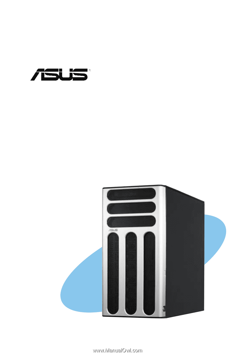
TS300-E3/PA4 & PS4
Intel
®
Pentium
®
4/Pentium
®
D LGA775
Pedestal/5U Rackmount Server
1066/800 MHz Front Side Bus