Asus TS300-E3 PA4 TS300-E3 - Page 45
Back side
 |
View all Asus TS300-E3 PA4 manuals
Add to My Manuals
Save this manual to your list of manuals |
Page 45 highlights
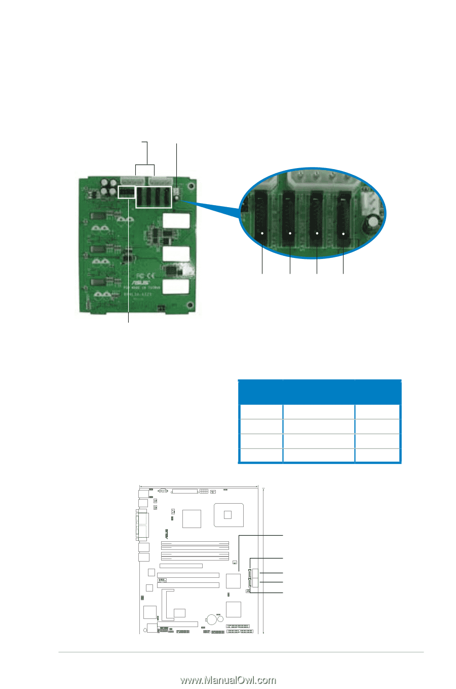
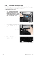
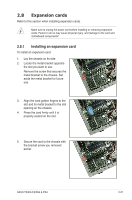
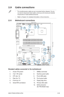
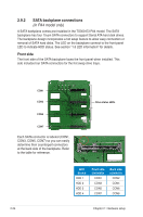
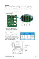
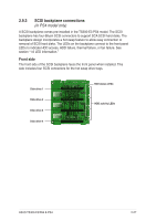
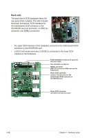
Back side The back side of SATA backplane faces the rear panel when installed. This side includes the power connectors, SATA interfaces for the motherboard Serial ATA connectors or the SATA/RAID card, an HDD fan connector, and SMBus connectors. Power connectors (connect power plugs from the power supply) Fan connector (for HDD fan) CON2 CON4 CON6 CON8 Upper 6-1 pins: SMBus connector (connects the SMB cable from the BPSMB1 connector on the motherboard) The back side SATA connectors are attached to the motherboard SATA connectors via the supplied SATA cables. Refer to the illustration below for the location of the SATA connectors. Refer to the table on the right for the default SATA cable connections. Backplane ID CON2 CON4 CON6 CON8 Connected to (on motherboard) SATA1 SATA2 SATA3 SATA4 Controlled by Intel® ICH7R Intel® ICH7R Intel® ICH7R Intel® ICH7R PS/2KBMS KBPWR1 T: Mouse PSUSMB1 B: Keyboard USBPW12 USB12 REAR_FAN1 25cm (9.8in) ATXPWR1 ATX12V1 CPU_FAN1 COM1 REAR_FAN2 CPU_FAN2 FM_CPU2 Intel E7230 FM_CPU1 LGA775 PARALLEL PORT ® P5MT LAN_EN1 LAN_EN2 VGA1 LAN1 LAN2 Broadcom BCM5721 Broadcom BCM5721 DDR2 DIMM_A1 (64 bit,240-pin module) DDR2 DIMM_A2 (64 bit,240-pin module) DDR2 DIMM_B1 (64 bit,240-pin module) DDR2 DIMM_B2 (64 bit,240-pin module) PCIE1 PCIX2 COM2 PCIX3 FRNT_FAN1 Intel ICH7R SATA4 SATA3 SATA2 SATA1 RAID_SEL1 FRNT_FAN2 VGA_EN1 BMCSOCKET1 ATI RAGE XL VGA Controller Super I/O SB_PWR1 8Mbit Flash BIOS RECOVERY1 PCI4 BPSMB1 TRPWR1 AUX_PANEL1 BMCCONN1 HDLED1 CLRTC1 CR2032 3V Lithium Cell CMOS Power BUZZ1 USBPW34 USB34 PANEL1 Intel 6702 PXH FLOPPY1 PRI_IDE1 30.5cm (12in) SATA RAID controller SATA4 SATA2 SATA1 SATA3 ASUS TS300-E3/PA4 & PS4 2-25
-
 1
1 -
2
-
3
-
4
-
5
-
6
-
7
-
8
-
9
-
10
-
11
-
12
-
13
-
14
-
15
-
16
-
17
-
18
-
19
-
20
-
21
-
22
-
23
-
24
-
25
-
26
-
27
-
28
-
29
-
30
-
31
-
32
-
33
-
34
-
35
-
36
-
37
-
38
-
39
-
 40
40 -
 41
41 -
 42
42 -
 43
43 -
 44
44 -
 45
45 -
 46
46 -
 47
47 -
 48
48 -
 49
49 -
 50
50 -
51
-
52
-
53
-
54
-
55
-
56
-
57
-
58
-
59
-
60
-
61
-
62
-
63
-
64
-
65
-
66
-
67
-
68
-
69
-
70
-
71
-
72
-
73
-
74
-
75
-
76
-
77
-
78
-
79
-
80
-
81
-
82
-
83
-
84
-
85
-
86
-
87
-
88
-
89
-
90
-
91
-
92
-
93
-
94
-
95
-
96
-
97
-
98
-
99
-
100
-
101
-
102
-
103
-
104
-
105
-
106
-
107
-
108
-
109
-
110
-
111
-
112
-
113
-
114
-
115
-
116
-
117
-
118
-
119
-
120
-
121
-
122
-
123
-
124
-
125
-
126
-
127
-
128
-
129
-
130
-
131
-
132
-
133
-
134
-
135
-
136
-
137
-
138
-
139
-
140
-
141
-
142
-
143
-
144
-
145
-
146
-
147
-
148
-
149
-
150
-
151
-
152
-
153
-
154
-
155
-
156
-
157
-
158
-
159
-
160
-
161
-
162
-
163
-
164
-
165
-
166
-
167
-
168
-
169
-
170
-
171
-
172
-
173
-
174
-
175
-
176
-
177
-
178
-
179
-
180
-
181
-
182
-
183
-
184
-
185
-
186
-
187
-
188
-
189
-
190
-
191
-
192
-
193
-
194
-
195
-
196
-
197
-
198
-
199
-
200
-
201
-
202
-
203
-
204
 |
 |