Asus Terminator P4 533 Terminator P4-533 English user''''s manual - Page 14
Internal Features
 |
View all Asus Terminator P4 533 manuals
Add to My Manuals
Save this manual to your list of manuals |
Page 14 highlights
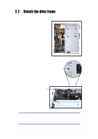
1.3 Internal Features The figure below shows the internal view of the system when you remove the cover and flip out the drive frame. You will see here the standard components that come already installed in the system and the places where you can install the other required components to get the system running. Game/MIDI/COM1 Extension Module Two 5.25" 3.5" HDD Drive Bays Drive Bay 3.5" Floppy Drive Modem Card (optional) Motherboard USB/audio Board Power Supply 14 Chapter 1: System Introduction
-
 1
1 -
2
-
3
-
4
-
5
-
6
-
7
-
8
-
 9
9 -
 10
10 -
 11
11 -
 12
12 -
 13
13 -
 14
14 -
 15
15 -
 16
16 -
 17
17 -
 18
18 -
 19
19 -
20
-
21
-
22
-
23
-
24
-
25
-
26
-
27
-
28
-
29
-
30
-
31
-
32
-
33
-
34
-
35
-
36
-
37
-
38
-
39
-
40
-
41
-
42
-
43
-
44
-
45
-
46
-
47
-
48
-
49
-
50
-
51
-
52
-
53
-
54
-
55
-
56
-
57
-
58
-
59
-
60
-
61
-
62
-
63
-
64
-
65
-
66
-
67
-
68
-
69
-
70
-
71
-
72
-
73
-
74
-
75
-
76
-
77
-
78
-
79
-
80
-
81
-
82
-
83
-
84
-
85
-
86
-
87
-
88
-
89
-
90
-
91
-
92
-
93
-
94
-
95
-
96
-
97
-
98
 |
 |

14
Chapter 1:
System Introduction
1.3
Internal Features
The figure below shows the internal view of the system when you remove
the cover and flip out the drive frame. You will see here the standard
components that come already installed in the system and the places
where you can install the other required components to get the system
running.
Motherboard
Power Supply
Modem Card
(optional)
USB/audio
Board
Two 5.25”
Drive Bays
3.5” HDD
Drive Bay
3.5” Floppy Drive
Game/MIDI/COM1
Extension Module