Asus Terminator P4 533 Terminator P4-533 English user''''s manual - Page 50
Motherboard information, Front panel audio connectors 5-1 pin MIC_LOUT1, IO extension
 |
View all Asus Terminator P4 533 manuals
Add to My Manuals
Save this manual to your list of manuals |
Page 50 highlights
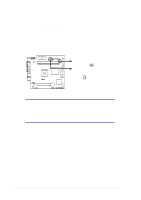
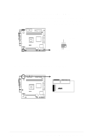
8. Front panel audio connectors (5-1 pin MIC_LOUT1) This connector connects to a front panel audio module using an audio cable. If your chassis has this audio module, you may conveniently connect a microphone and a speaker/headphone on the front panel. P4SC-E MIC_LOUT1 Head set Left channel Head set Right channel GND ® P4SC-E Microphone Header 1 1 MIC PWR MIC Signal 9. IO extension module connector (22-pin IOC_MB) This connector is for the CGAEX extension module. P4SC-E ® P4SC-E IOC_MB Connector COM1 GAME ® CGAEX IOC_DC 50 Chapter 3: Motherboard information
-
 1
1 -
2
-
3
-
4
-
5
-
6
-
7
-
8
-
9
-
10
-
11
-
12
-
13
-
14
-
15
-
16
-
17
-
18
-
19
-
20
-
21
-
22
-
23
-
24
-
25
-
26
-
27
-
28
-
29
-
30
-
31
-
32
-
33
-
34
-
35
-
36
-
37
-
38
-
39
-
40
-
41
-
42
-
43
-
44
-
 45
45 -
 46
46 -
 47
47 -
 48
48 -
 49
49 -
 50
50 -
 51
51 -
 52
52 -
 53
53 -
 54
54 -
 55
55 -
56
-
57
-
58
-
59
-
60
-
61
-
62
-
63
-
64
-
65
-
66
-
67
-
68
-
69
-
70
-
71
-
72
-
73
-
74
-
75
-
76
-
77
-
78
-
79
-
80
-
81
-
82
-
83
-
84
-
85
-
86
-
87
-
88
-
89
-
90
-
91
-
92
-
93
-
94
-
95
-
96
-
97
-
98
 |
 |

50
Chapter 3:
Motherboard information
8.
Front panel audio connectors (5-1 pin MIC_LOUT1)
This connector connects to a front panel audio module using an audio
cable. If your chassis has this audio module, you may conveniently
connect a microphone and a speaker/headphone on the front panel.
P4SC-E
P4SC-E Microphone Header
MIC_LOUT1
1
MIC Signal
MIC PWR
Head set Left channel
GND
Head set Right channel
1
9.
IO extension module connector (22-pin IOC_MB)
This connector is for the CGAEX extension module.
P4SC-E
P4SC-E IOC_MB Connector
®
CGAEX
COM1
GAME
IOC_DC