Asus Terminator P4 533 Terminator P4-533 English user''''s manual - Page 18
Basic Installation
 |
View all Asus Terminator P4 533 manuals
Add to My Manuals
Save this manual to your list of manuals |
Page 18 highlights
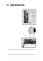
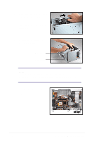
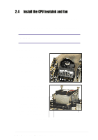
3. Place your thumb on the right edge of the power socket module, then slide the module to the right until it is completely detached from the rear panel. 4. Unlatch the drive frame by pulling it outward. Drive frame Swivel edge NOTE The drive frame has a swivel (hinge-like) edge that is attached to the main chassis. It is not necessary to completely detach the drive frame from the chassis when installing components. 5. Carefully lay the drive frame alongside the main chassis frame. 18 Chapter 2: Basic Installation
-
 1
1 -
2
-
3
-
4
-
5
-
6
-
7
-
8
-
9
-
10
-
11
-
12
-
 13
13 -
 14
14 -
 15
15 -
 16
16 -
 17
17 -
 18
18 -
 19
19 -
 20
20 -
 21
21 -
 22
22 -
 23
23 -
24
-
25
-
26
-
27
-
28
-
29
-
30
-
31
-
32
-
33
-
34
-
35
-
36
-
37
-
38
-
39
-
40
-
41
-
42
-
43
-
44
-
45
-
46
-
47
-
48
-
49
-
50
-
51
-
52
-
53
-
54
-
55
-
56
-
57
-
58
-
59
-
60
-
61
-
62
-
63
-
64
-
65
-
66
-
67
-
68
-
69
-
70
-
71
-
72
-
73
-
74
-
75
-
76
-
77
-
78
-
79
-
80
-
81
-
82
-
83
-
84
-
85
-
86
-
87
-
88
-
89
-
90
-
91
-
92
-
93
-
94
-
95
-
96
-
97
-
98
 |
 |

18
Chapter 2:
Basic Installation
3.
Place your thumb on the right
edge of the power socket
module, then slide the module
to the right
until it is
completely detached from the
rear panel.
4.
Unlatch the drive frame by
pulling it outward.
NOTE
The drive frame has a swivel (hinge-like) edge that is attached to the
main chassis. It is not necessary to completely detach the drive frame
from the chassis when installing components.
5.
Carefully lay the drive frame
alongside the main chassis
frame.
Drive frame
Swivel edge