Asus Terminator P4 533 Terminator P4-533 English user''''s manual - Page 49
ASUS Terminator P4 533 Barebone System, USB 2.0 headers 10-1 pin USB_34, USB_56, Internal audio - sound
 |
View all Asus Terminator P4 533 manuals
Add to My Manuals
Save this manual to your list of manuals |
Page 49 highlights
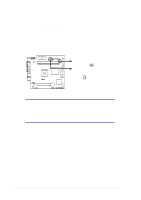
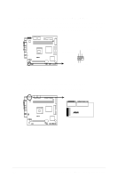
6. USB 2.0 headers (10-1 pin USB_34, USB_56) The USB_34 header is connected to the USB2P connector in the UAEX extension module on the front panel for two additional USB 2.0 ports. The USB_56 header (pins 6 to 10) is connected to the J1 connector on the card reader module on the front panel to support either Compact Flash card or Secure Digital (SD), Memory Stick (MS), MultiMedia Card (MMC), Smart Media cards. P4SC-E USB Power USBP2- USBP2+ GND NC USB Power USBP2- USBP2+ GND NC USB Power USBP3- USBP3+ GND USB Power USBP3- USBP3+ GND ® P4SC-E USB Ports 1 5 1 5 USB_34 USB_56 6 10 6 10 7. Internal audio connectors (4-pin AUX1, CD1, MODEM1) These connectors allow you to receive stereo audio input from sound sources such as a CD-ROM, TV tuner, or MPEG card. The MODEM connector allows the onboard audio to interface with a voice modem card with a similar connector. It also allows the sharing of mono_in (such as a phone) and a mono_out (such as a speaker) between the audio and a voice modem card. Left Audio Channel Ground Right Audio Channel Left Audio Channel Ground Right Audio Channel P4SC-E AUX1 (White) CD1 (Black) ® P4SC-E Internal Audio Connectors Modem-In (to Modem) Ground Modem-Out (from Modem) MODEM1 ASUS Terminator P4 533 Barebone System 49
-
 1
1 -
2
-
3
-
4
-
5
-
6
-
7
-
8
-
9
-
10
-
11
-
12
-
13
-
14
-
15
-
16
-
17
-
18
-
19
-
20
-
21
-
22
-
23
-
24
-
25
-
26
-
27
-
28
-
29
-
30
-
31
-
32
-
33
-
34
-
35
-
36
-
37
-
38
-
39
-
40
-
41
-
42
-
43
-
 44
44 -
 45
45 -
 46
46 -
 47
47 -
 48
48 -
 49
49 -
 50
50 -
 51
51 -
 52
52 -
 53
53 -
 54
54 -
55
-
56
-
57
-
58
-
59
-
60
-
61
-
62
-
63
-
64
-
65
-
66
-
67
-
68
-
69
-
70
-
71
-
72
-
73
-
74
-
75
-
76
-
77
-
78
-
79
-
80
-
81
-
82
-
83
-
84
-
85
-
86
-
87
-
88
-
89
-
90
-
91
-
92
-
93
-
94
-
95
-
96
-
97
-
98
 |
 |
