Asus V3-P5945GC User Manual - Page 40
Re-connecting cables
 |
UPC - 610839942145
View all Asus V3-P5945GC manuals
Add to My Manuals
Save this manual to your list of manuals |
Page 40 highlights
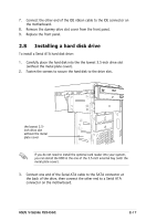
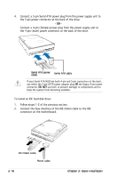
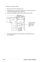
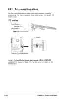
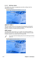
2.11 Re-connecting cables You may have disconnected some cables when you were installing components. You must re-connect these cables before you replace the chassis cover. LED cables Reset button HDD LED Power Switch Power LED F_PANEL R PWR LED PWR BTN HDLED RESET System Panel Connector GND PWR PLEDPLED+ Reset Ground IDELEDIDELED+ Connect the reset button, power switch, power LED, and HDD LED cables to their respective leads in the system panel connector on the motherboard. 2-22 Chapter 2: Basic installation
-
 1
1 -
2
-
3
-
4
-
5
-
6
-
7
-
8
-
9
-
10
-
11
-
12
-
13
-
14
-
15
-
16
-
17
-
18
-
19
-
20
-
21
-
22
-
23
-
24
-
25
-
26
-
27
-
28
-
29
-
30
-
31
-
32
-
33
-
34
-
 35
35 -
 36
36 -
 37
37 -
 38
38 -
 39
39 -
 40
40 -
 41
41 -
 42
42 -
 43
43 -
 44
44 -
 45
45 -
46
-
47
-
48
-
49
-
50
-
51
-
52
-
53
-
54
-
55
-
56
-
57
-
58
-
59
-
60
-
61
-
62
-
63
-
64
-
65
-
66
-
67
-
68
-
69
-
70
-
71
-
72
-
73
-
74
-
75
-
76
-
77
-
78
-
79
-
80
-
81
-
82
-
83
-
84
-
85
-
86
-
87
-
88
-
89
-
90
-
91
-
92
-
93
-
94
-
95
-
96
-
97
-
98
-
99
-
100
 |
 |

2-22
Chapter 2: Basic installation
2.11 Re-connecting cables
You may have disconnected some cables when you were installing
components. You must re-connect these cables before you replace the
chassis cover.
LED cables
Connect the
reset button,
power switch,
power LED, and
HDD LED
cables to their respective leads in the system panel connector on the
motherboard.
HDD LED
Power LED
Power Switch
Reset button
I
System Panel Connector
F_PANEL
Ground
PLED-
PWR
PLED+
GND
Reset
IDELED+
IDELED-
HD LED
RESET
PWR LED
PWR BTN