Asus VivoMini VM65N VivoMini V Seriese Barebone User Manual English - Page 36
Match the rubber heads with the four screw slots on the drive, Carefully
 |
View all Asus VivoMini VM65N manuals
Add to My Manuals
Save this manual to your list of manuals |
Page 36 highlights
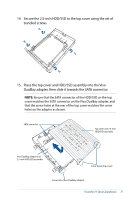
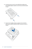
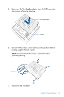
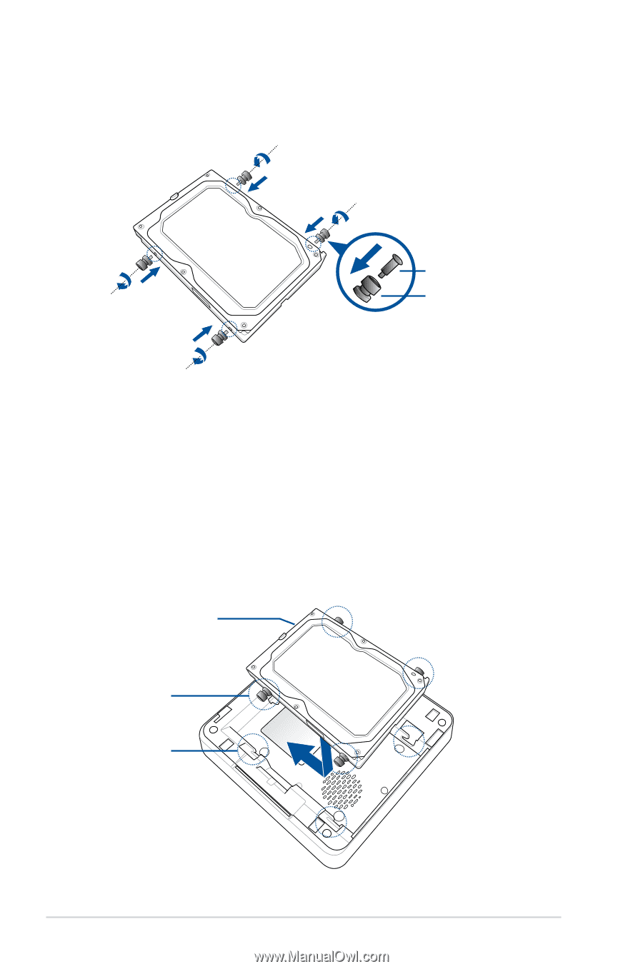
8. Attach each of the four black screws with rubber head assembly into the screw holes of the HDD as shown. Black screw Rubber head 9. Position the Serial ATA HDD on top of the drive bay to an orientation where the HDD's SATA connectors are aligned to the SATA connector in the VivoMini drive bay. 10. Match the rubber heads with the four screw slots on the drive bay. 11. Carefully, place the Serial ATA HDD into the drive bay, then slide the drive towards the SATA connector. SATA connector Rubber head Screw slot 36 VivoMini V Series Barebone
-
 1
1 -
2
-
3
-
4
-
5
-
6
-
7
-
8
-
9
-
10
-
11
-
12
-
13
-
14
-
15
-
16
-
17
-
18
-
19
-
20
-
21
-
22
-
23
-
24
-
25
-
26
-
27
-
28
-
29
-
30
-
 31
31 -
 32
32 -
 33
33 -
 34
34 -
 35
35 -
 36
36 -
 37
37 -
 38
38 -
 39
39 -
 40
40 -
 41
41 -
42
-
43
-
44
-
45
-
46
-
47
-
48
-
49
-
50
-
51
-
52
-
53
-
54
 |
 |
36
VivoMini V Series Barebone
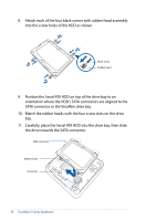
8.
Attach each of the four black screws with rubber head assembly
into the screw holes of the HDD as shown.
9.
Position the Serial ATA HDD on top of the drive bay to an
orientation where the HDD’s SATA connectors are aligned to the
SATA connector in the VivoMini drive bay.
10.
Match the rubber heads with the four screw slots on the drive
bay.
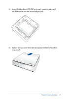
11.
Carefully, place the Serial ATA HDD into the drive bay, then slide
the drive towards the SATA connector.
SATA connector
Rubber head
Rubber head
Screw slot
Black screw