Asus X900-PIB P3C-E User Manual - Page 22
System Memory
 |
View all Asus X900-PIB manuals
Add to My Manuals
Save this manual to your list of manuals |
Page 22 highlights
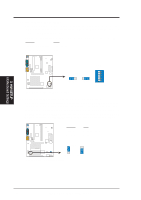
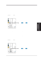
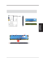
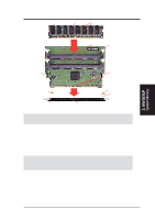
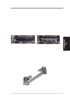
3. H/W SETUP System Memory 3. HARDWARE SETUP 3.5 System Memory NOTE: No hardware or BIOS setup is required after adding or removing memory. This motherboard has two Rambus Inline Memory Module (RIMM) sockets. These sockets support Direct RDRAMs (both ECC and non-ECC are supported) in 64, 96, 128, 192, and 256MB densities. With an optional ASUS DIMM Riser, unbuffered Synchronous Dynamic Random Access Memory (SDRAM, 3.3V power level) in 16, 32, 64, 128, 256, or 512MB densities can also be used on these sockets. The chipset's Error Checking and Correction (ECC) feature is available only when using RDRAMs. ECC feature is not available when using SDRAM (ECC and nonECC) with an ASUS DIMM Riser. For memory speed setup, see 4.4.1 CHIP Configuration. Install memory in any combination as follows: Location Memory Module RIMM0 (Rows 0&1) RDRAM (do not use when SDRAM is used) C-RIMM (use when socket will not be populated) RIMM1 (Rows 2&3) RDRAM (do not use when SDRAM is used) C-RIMM (use when socket will not be populated) TOTAL SYSTEM MEMORY (RDRAM: 1GB Max) / (SDRAM: 1GB Max) Subtotal x 1 x 1 = IMPORTANT 1. When using RDRAM as memory, the RIMM sockets must be populated in the following sequence: RIMM0 and then RIMM1. 2. To use SDRAM with this motherboard, an ASUS DIMM Riser (ASUS DR2) must be installed as an interface (see 3.5.2 Installing Memory Using the ASUS DIMM Riser). The riser must be inserted into RIMM0, with RIMM1 populated with C-RIMM. 3. C-RIMMs (Continuity RIMM) must be used to complete the sockets that are not populated by either RDRAMs or an ASUS DIMM Riser (when using SDRAM). C-RIMM is necessary to avoid breaking the signal lines, which are a serial connection in a Rambus interface, such as used in this motherboard. This assures the electrical integrity of a Rambus interface. 4. DO NOT mix RDRAMs with an SDRAM+Riser or vice versa. 22 ASUS P3C-E User's Manual
-
 1
1 -
2
-
3
-
4
-
5
-
6
-
7
-
8
-
9
-
10
-
11
-
12
-
13
-
14
-
15
-
16
-
 17
17 -
 18
18 -
 19
19 -
 20
20 -
 21
21 -
 22
22 -
 23
23 -
 24
24 -
 25
25 -
 26
26 -
 27
27 -
28
-
29
-
30
-
31
-
32
-
33
-
34
-
35
-
36
-
37
-
38
-
39
-
40
-
41
-
42
-
43
-
44
-
45
-
46
-
47
-
48
-
49
-
50
-
51
-
52
-
53
-
54
-
55
-
56
-
57
-
58
-
59
-
60
-
61
-
62
-
63
-
64
-
65
-
66
-
67
-
68
-
69
-
70
-
71
-
72
-
73
-
74
-
75
-
76
-
77
-
78
-
79
-
80
-
81
-
82
-
83
-
84
-
85
-
86
-
87
-
88
-
89
-
90
-
91
-
92
-
93
-
94
-
95
-
96
-
97
-
98
-
99
-
100
-
101
-
102
-
103
-
104
-
105
-
106
-
107
-
108
-
109
-
110
 |
 |
