Axis Communications Q1765-LE Q1765-LE - User Manual - Page 55
Multi-Connector Cable sold separately
 |
View all Axis Communications Q1765-LE manuals
Add to My Manuals
Save this manual to your list of manuals |
Page 55 highlights
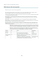
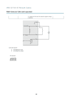
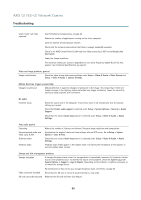
AXIS Q1765-LE Network Camera Multi-Connector Cable (sold separately) Multi-Connector Cable (sold separately) When connecting external equipment to the Axis product, a multi-connector cable (available from Axis) is required in order to maintain the product's IP rating. The multi-connector cable can be purchased from your Axis reseller. Connect the multi-connector cable to the product's multi-connector. To locate the multi-connector, see Hardware Overview, on page 6 . The cable provides the following connectors: Power connector - 2-pin terminal block used for power input. The polarity of the cables does not matter. Use a Safety Extra Low Voltage (SELV) compliant limited power source (LPS) with either a rated output power limited to ≤100 W or a rated output current limited to ≤5 A. Audio in (pink) - 3.5 mm input for a mono microphone, or a line-in mono signal (left channel is used from a stereo signal). Audio out (green) - 3.5 mm output for audio (line level) that can be connected to a public address (PA) system or an active speaker with a built-in amplifier. A stereo connector must be used for the audio out. I/O terminal connector - Use with external devices in combination with, for example, tampering alarms, motion detection, event triggering, time lapse recording and alarm notifications. In addition to the 0 V DC reference point and power (DC output), the I/O connector provides the interface to: • Digital output - For connecting external devices such as relays and LEDs. Connected devices can be activated by the VAPIX® Application Programming Interface, output buttons on the Live View page or by an Action Rule. The output will show as active (shown under System Options > Port & Devices > Port Status) if the alarm device is activated. • Digital input - An alarm input for connecting devices that can toggle between an open and closed circuit, for example: PIRs, door/window contacts, glass break detectors, etc. When a signal is received the state changes and the input becomes active (shown under System Options > Port & Devices > Port Status). Function Pin 0 V DC (-) 1 DC output 2 Configurable (Input 3-4 or Output) Notes Specifications 0 V DC Can be used to power auxiliary equipment. Note: This pin can only be used as power out. 12 V DC Max load =50 mA Digital input - Connect to pin 1 to activate, or leave floating (unconnected) to deactivate. 0 to max 30 V DC Digital output - Connected to pin 1 when activated, 0 to max 30 V DC, open floating (unconnected) when deactivated. If used with drain, 100 mA an inductive load, e.g. a relay, a diode must be connected 55
-
 1
1 -
2
-
3
-
4
-
5
-
6
-
7
-
8
-
9
-
10
-
11
-
12
-
13
-
14
-
15
-
16
-
17
-
18
-
19
-
20
-
21
-
22
-
23
-
24
-
25
-
26
-
27
-
28
-
29
-
30
-
31
-
32
-
33
-
34
-
35
-
36
-
37
-
38
-
39
-
40
-
41
-
42
-
43
-
44
-
45
-
46
-
47
-
48
-
49
-
 50
50 -
 51
51 -
 52
52 -
 53
53 -
 54
54 -
 55
55 -
 56
56 -
 57
57 -
 58
58 -
 59
59 -
 60
60 -
61
-
62
-
63
-
64
 |
 |
